2 Installation
MICROMASTER 430 Operating Instructions
30 6SE6400-5AC00-0BP0
2.4.4 Screening Methods
Frame Size C
For frame size C the Gland Plate Kit is supplied as an option. It allows easy and
efficient connection of the necessary screening. See the Gland Plate Installation
Instructions contained on the Document CD-ROM, supplied with the MM430.
Frame Sizes D, E and F
The Gland Plate is factory fitted. The installation of the screening is accomplished
using the same methodology as in frame size C.
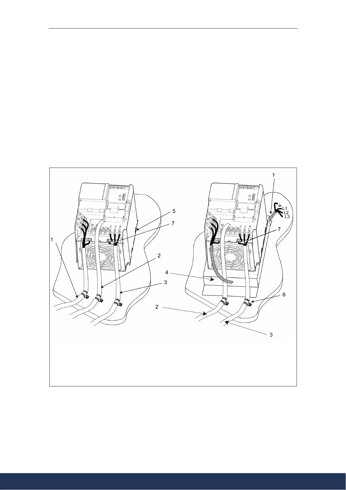
Screening without a Gland Plate
Should a Gland Plate not be available, then the inverter can be screened using the
methodology shown in Figure 2-7.
1
ains power input
2 Control cable
3 Motor cable
4 Footprint filte
5 Metal back plate
6 Use suitable clips to fix motor and control cable screens securely to metal back plate
7 Screening cables
Figure 2-7 Wiring Guidelines to Minimize the Effects of EMI
www.eltra-trade.com
+421 552 601 099
info@eltra-trade.com