EasyManuals Logo

Siemens MICROMASTER 430 Manual

Siemens MICROMASTER 430
110 pages
To Next Page IconTo Next Page
To Previous Page IconTo Previous Page
Page #55 background imageLoading...
Page #55 background image
4 MICROMASTER 430 functions
MICROMASTER 430 Operating Instructions
54 6SE6400-5AC00-0BP0
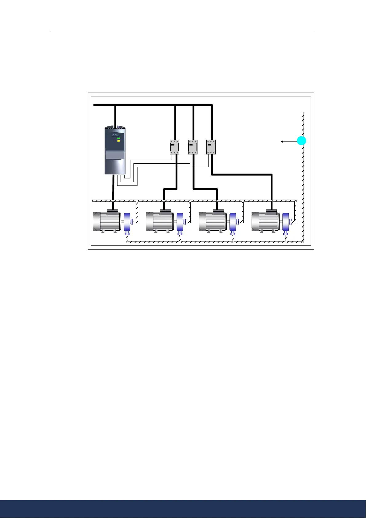
4.5.3 Motor Staging
Controlling additional drives via output relay
Mains
Inverter Motor Starters
Pressure Sensor
To Inverter PID Input
Figure 4-3 Motor Staging
Function
Enables up to three additional motors to be controlled based on PID control
The entire system is made up of a pump which is controlled by the inverter with up
to an additional 3 pumps which can be added to the system via contactors or motor
starters.The motor starter is controlled via the output relay in the inverter. Figure
4-3 shows a typical pump system.
This function can also be used accordingly for ventilators and ventilation shafts.
For additional settings please refer to parameter list P2370 and following.
www.eltra-trade.com
+421 552 601 099
info@eltra-trade.com

Table of Contents

Other manuals for Siemens MICROMASTER 430

Questions and Answers:

Question and Answer IconNeed help?

Do you have a question about the Siemens MICROMASTER 430 and is the answer not in the manual?

Siemens MICROMASTER 430 Specifications

General IconGeneral
Power Range7.5 kW to 250 kW
Voltage Range380V to 480V
Frequency Range0 Hz to 650 Hz
Protection ClassIP20
Input Frequency47 Hz to 63 Hz
Digital Inputs6
Cooling MethodForced-air cooling
CommunicationUSS
Protection FeaturesOvervoltage, undervoltage, overcurrent, short-circuit, ground fault, overtemperature
Analog Inputs2
Digital Outputs3
Analog Outputs2
Ambient Temperature-10°C to +50°C
Control TypeSensorless vector control

Related product manuals