3 Commissioning
MICROMASTER 430 Operating Instructions
6SE6400-5AC00-0BP0
39
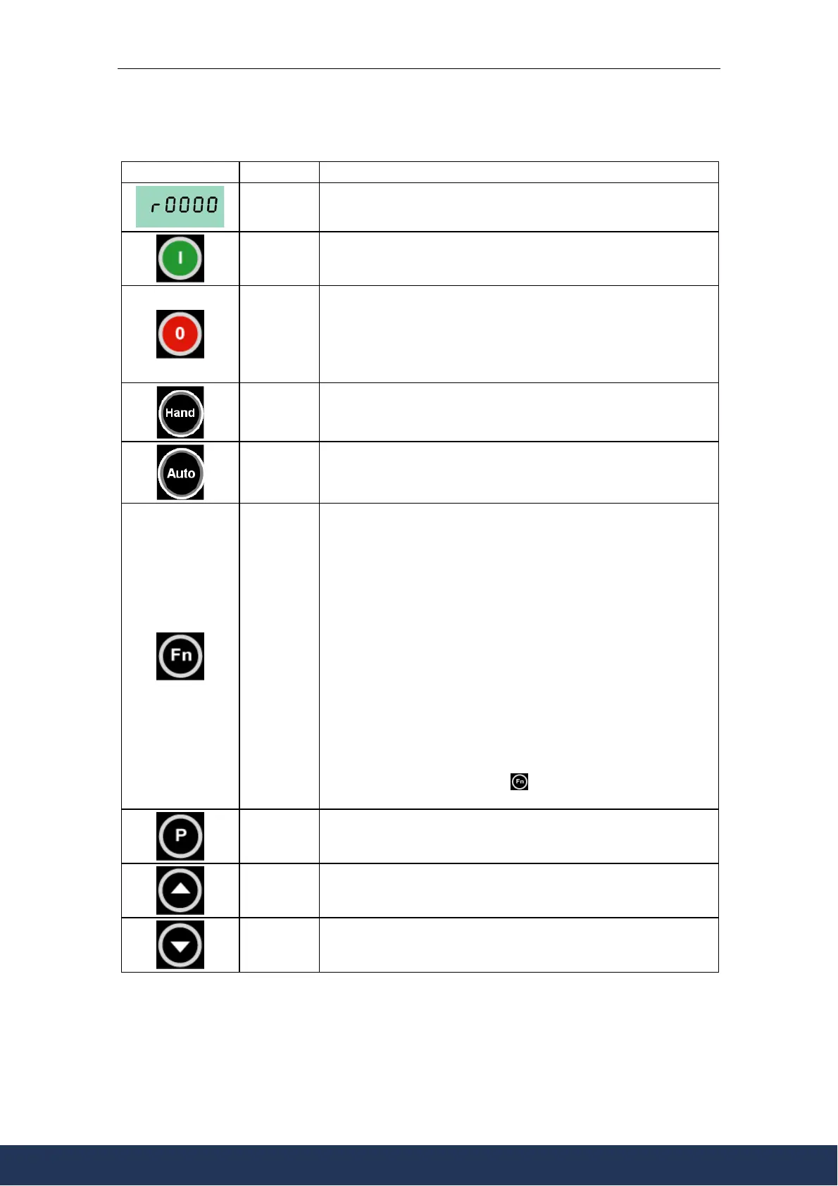
Buttons on the BOP-2
Panel/Button Function Effects
Indicates
Status
The LCD displays the settings currently used by the converter.
Start motor
Pressing the button starts the converter. This button is disabled by
default. To enable this button set P0700 = 1.
Stop motor
OFF1 Pressing the button causes the motor to come to a standstill
at the selected ramp down rate. Disabled by default; to enable set
P0700 = 1.
OFF2 Pressing the button twice (or once long) causes the motor to
coast to a standstill.
This function is always enabled.
Manual
mode
The customer terminal strip (CD S0) and the operating panel (BOP-
2) are sources for commands and set values
Automatic
mode
The customer’s terminal strip (CD S1) or the serial (US S) or field bus
interface (e.g. PROFIBUS) are sources for commands and set
values.
Functions
This button can be used to view additional information.
Pressing and holding the button for 2 seconds from any parameter
during operation, shows the following:
1. DC link voltage (indicated by d – units V).
2. Output current. (A)
3. Output frequency (Hz)
4. Output voltage (indicated by o – units V).
5. The value selected in P0005 (If P0005 is set to show any of the
above (3, 4, or 5) then this will not be shown again).
Additional presses will toggle around the above displays.
Jump Function
From any parameter (rXXXX or PXXXX) a short press of the Fn
button will immediately jump to r0000, you can then change another
parameter, if required. Upon returning to r0000, pressing the Fn
button will return you to your starting point.
Quit
In case of a fault or alarm the button resets the fault or
alarm message on the operator panel display.
Access
parameters
Pressing this button allows access to the parameters.
Increase
value
Pressing this button increases the displayed value.
Decrease
value
Pressing this button decreases the displayed value.
Figure 3-5 Buttons on the BOP-2
www.eltra-trade.com
+421 552 601 099
info@eltra-trade.com