Description
3.6 Functions
MicroSAM
40 Operating Instructions, 06/2012, C79000-G5376-C560-07
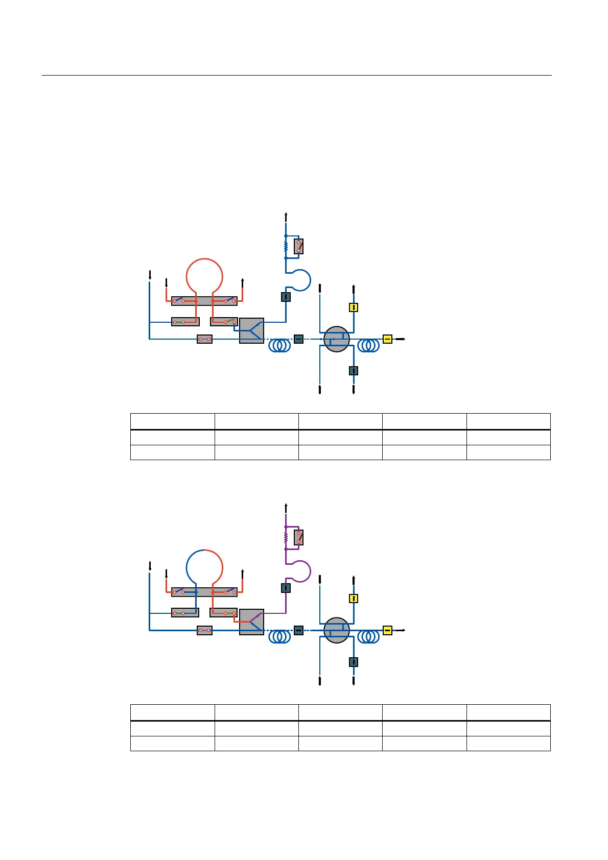
eLive
In this version, the procedure is carried out in two steps at different times:
Step - 1 - time switching point t
4
= - 10 s: The contents of the sample loop are set to the
pressure level of the carrier gas via MV1.
%XIIHU
9ROXPH
&ROXPQ
7&'%
7&'%
7&'$
7&'
&ROXPQ
6DPSOH
2XW
&*
09
09
09
09
09
09
6DPSOH
,Q
/RRS
6DPSOH
(3&
(3&
7&'$
%DFNIOXVK
(3&
/LYH
,QMHFWLRQ
/LYH
6ZLWFKLQJ
MV1 MV2 MV3 MV4 MV5
Flush loop_1 Sample Backflush Injection Flush loop_2
ON ON OFF OFF OFF
Step 2 - time switching point t
5
= -4 s: The contents of the sample loop are transferred to the
outlet "Backflush" by means of MV5 and the live injection.
%XIIHU
9ROXPH
&ROXPQ
7&'%
7&'%
7&'$
7&'
&ROXPQ
6DPSOH
2XW
&*
09
09
09
09
09
09
6DPSOH
,Q
/RRS
6DPSOH
(3&
(3&
7&'$
%DFNIOXVK
(3&
/LYH
,QMHFWLRQ
/LYH
6ZLWFKLQJ
MV1 MV2 MV3 MV4 MV5
Flush loop_1 Sample Backflush Injection Flush loop_2
ON ON OFF OFF ON