Mounting
4.4 Mounting and connecting
MicroSAM
Operating Instructions, 06/2012, C79000-G5376-C560-07
65
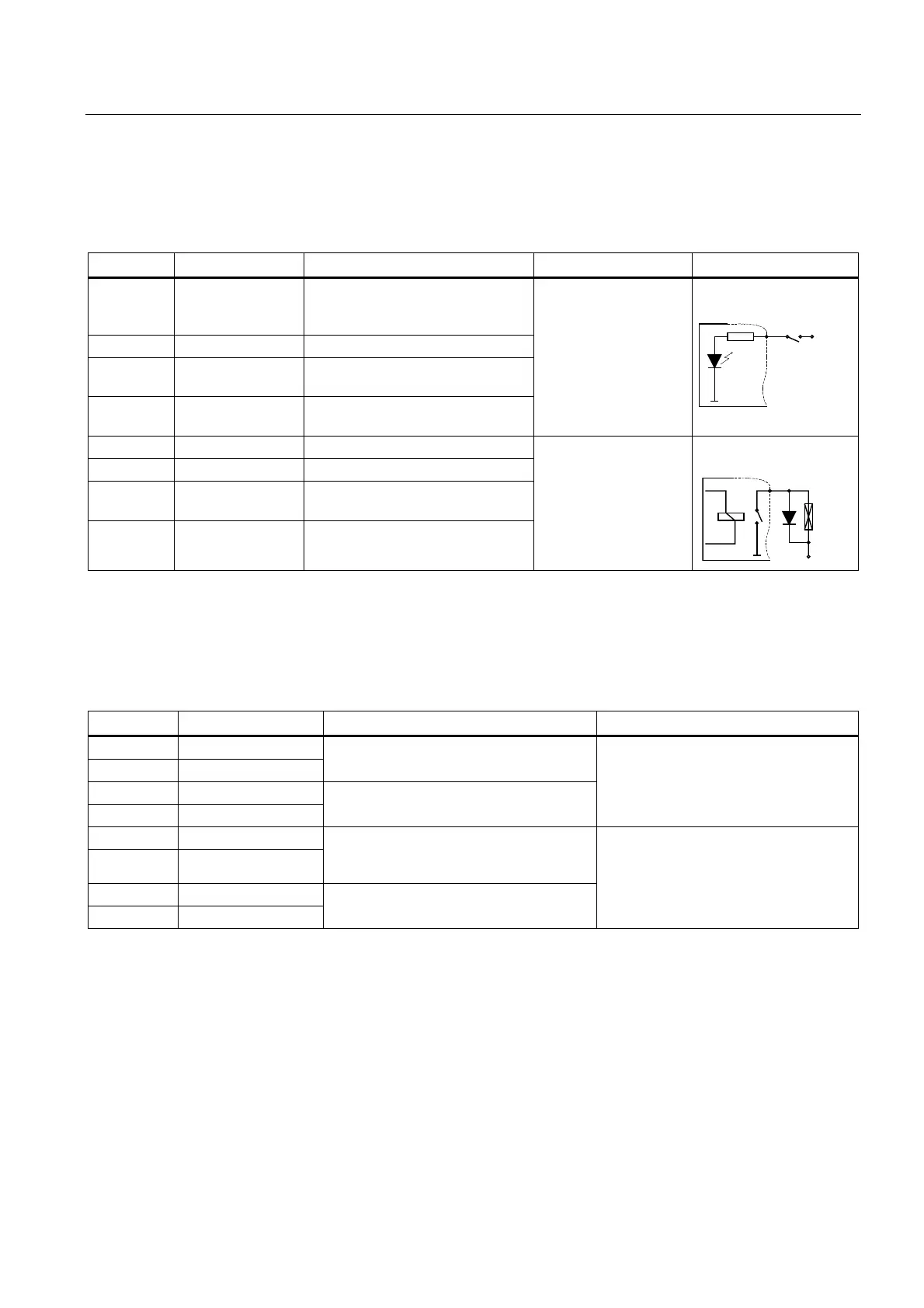
4.4.11 Connecting of digital outputs and digital inputs
The following table is valid for devices from release version 4 onwards.
Core color Description Usage Comment Circuit diagram
White/gray Digital input 1+ Sample flow,
24 V DC = OK,
0 V = too low
Gray/brown Digital input 2+ Application programmable
White/red Digital input 3+ or
SSSI* SCL-Rx
Application programmable
Brown/red Digital input 4+ or
SSSI* SDA-Rx
Application programmable
24 V DC to optocoupler
Second connection to
+24 V DC
9
Brown/blue Digital output 1+ Application programmable
White/blue Digital output 2+ Application programmable
White/pink Digital output 3+ or
SSSI* SCL-Tx
Application programmable
Pink/brown Digital output 4+ or
SSSI* SDA-Tx
Application programmable
Relay contact
0.5 A / 100 V / 10 W
Second connection to
+24 V DC
9
* The SSSI signals from devices are available with release version 10. The signals are used,
for example, to connect an IO extender (order no. A5E01494354). Refer to the
documentation of the IO extender for more on this. If SSSI is not used, the lines are available
for their original function as digital inputs and outputs.
The following table is valid for devices up to and including release version 3.
Core color Description Usage Comment
White/gray Digital output 1+
Gray/brown Digital output 1-
White/red Digital output 2+
Brown/red Digital output 2-
Relay contact
0.5 A / 100 V / 10 W
Brown/blue Digital input 1+
White/blue Digital input 1-
Sample flow,
24 V DC = OK,
0 V = too low
White/pink Digital input 2+
Pink/brown Digital input 2-
24 V DC to optocoupler
Arc-suppression diode with inductive loads
If you connect inductive loads (e.g. valves) for digital outputs, you must connect the arc-
suppression diodes in parallel.
Type of cable
Siemens AG recommends twisted-pair cables, 0.14 mm
2
(AWG 26).