Description
3.6 Functions
MicroSAM
26 Operating Instructions, 06/2012, C79000-G5376-C560-07
3.6.1 Gas flow charts
As of AS09, the MicroSAM gas chromatograph is manufactured as two versions: Live and
eLive.
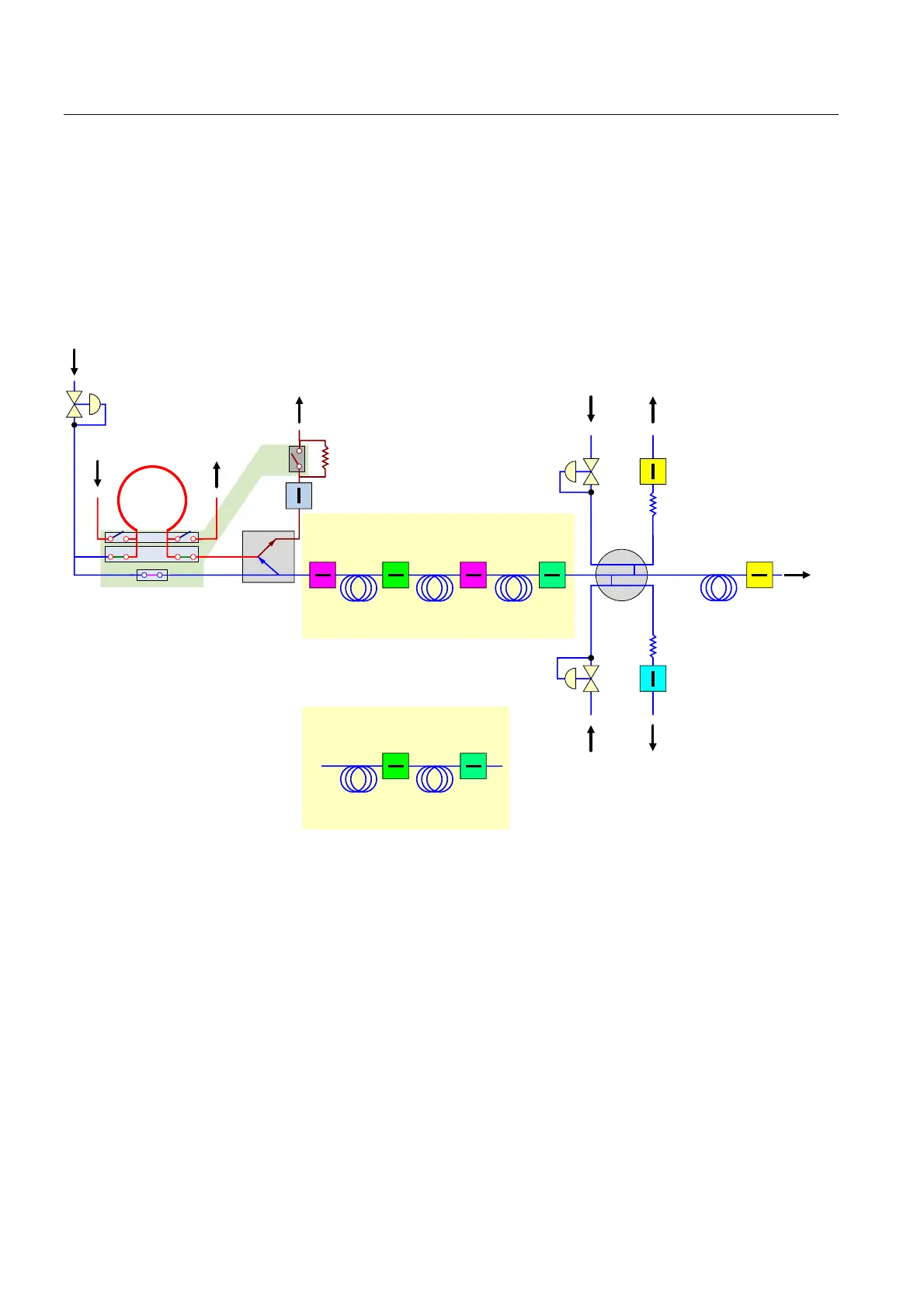
Solenoid valves control the respective functions in the multi-membrane valve.
Gas flow chart for analysis modules A01 - A11 (live injection)
&DUULHUJDV
(3&
(3& 7&'%
7&'%
7&'$
7&'$
(3&
6DPSOH
LQOHW
6DPSOH
RXWOHW
/LYH
,QMHFWLRQ
%DFNIOXVKLQJ
VDPSOHIORZ
/LYH
FROXPQ
VZLWFKLQJ
7&'%7&'$
A01 ... A03
7&'$7&'%
&ROXPQ
D
&ROXPQ
E
&ROXPQ
7&'$
A04 ... A11
7&'%
&ROXPQ
D
&ROXPQ
E
&ROXPQ
09
09
09
09
09
09
6DPSOH
ORRS
Solenoid valve 1 (MV1) Membrane valve function 1: "Bring sample loop to pressure of EPC 1, and purge"
Solenoid valve 2 (MV2) Membrane valve function 2: "Purge sample loop with sample"
Solenoid valve 3 (MV3) Membrane valve function 3: "Empty sample loop completely"
Solenoid valve 4 (MV4) Membrane valve function 4: "Inject"
EPC Electronic pressure control
TCD Thermal conductivity detector
Figure 3-5 Analysis module of type A with live injection