Preparing installation
110-0084.9 / 15 NXAIR / ≤ 40 kA 13
To install the switchgear, the switchgear room must have certain minimum dimensions.
Depending on the room height, the pressure relief system of the switchgear must be designed with evacuation
ducts leading out of the switchgear building:
Height of switchgear
room [mm]
Rated short-time
withstand current
I
k
[kA]
Switchgear with
evacuation ducts
Switchgear with
evacuation ducts
or absorber
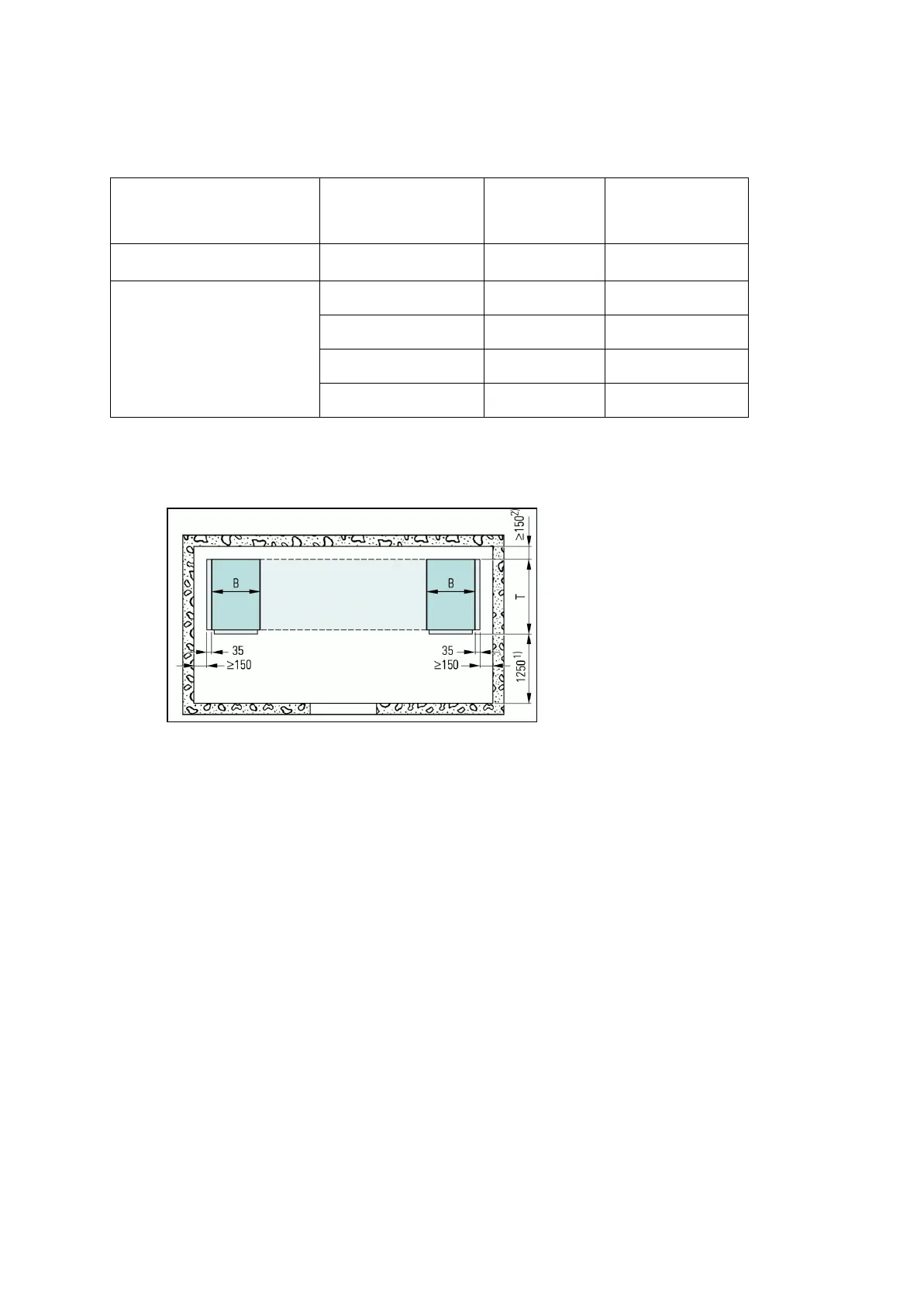
5.5 Switchgear with absorber
Fig. 5: Dimensions of the switchgear room, absorber
For panel replacement: Control aisle ≥ 1250 mm
For connection from the rear: ≥ 500 mm; also valid with rear connection duct
For contactor panel with panel width 435 mm: ≥ 100 mm
For a panel depth of 1540 mm: ≥ 110 mm
For further information, see information drawings NXAIR, order number 110-2300.9.
B = panel width / T = panel depth
complete

 Loading...


