110-0084.9 / 15 NXAIR / 40 kA 213
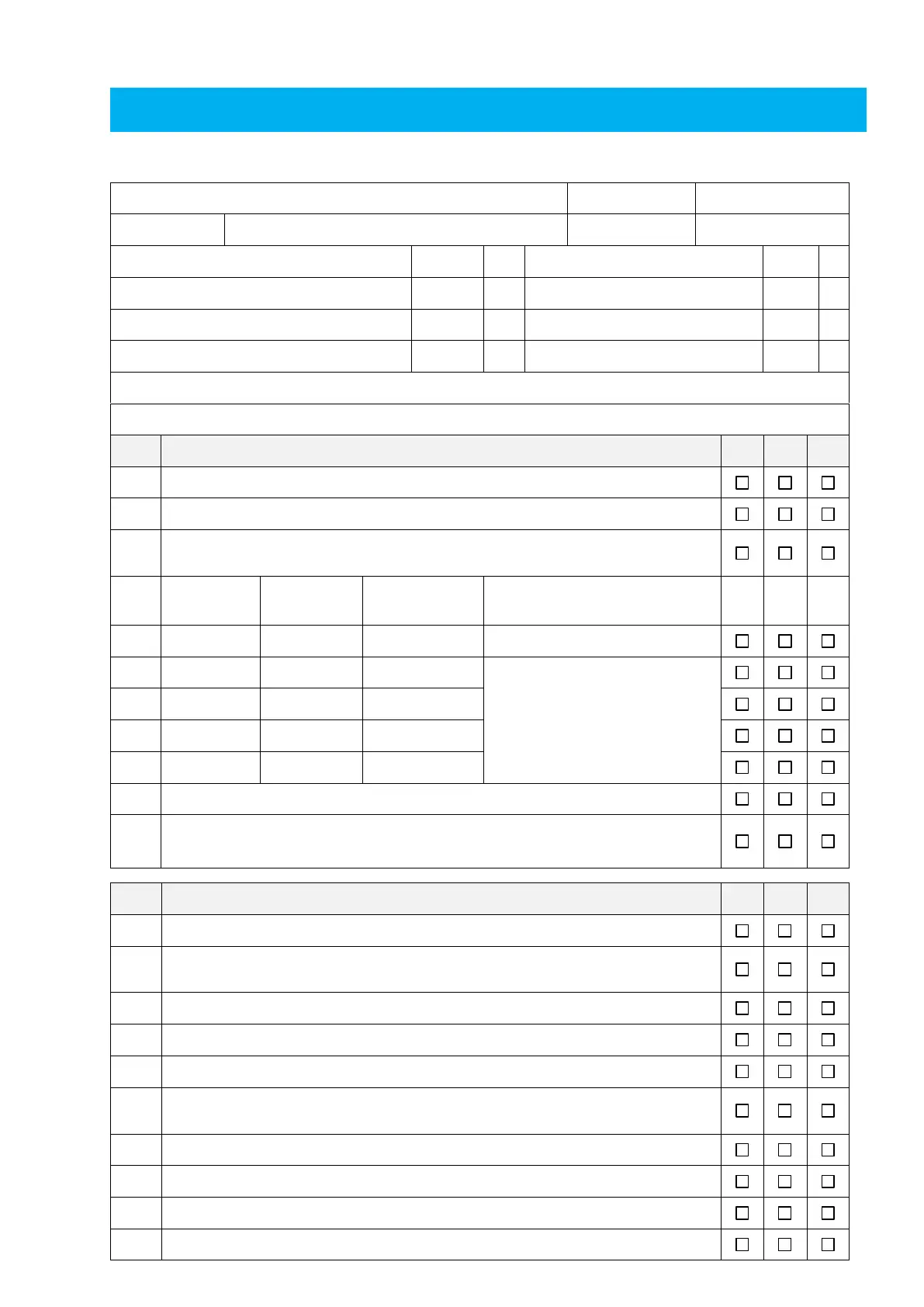
Installation report for air-insulated switchgear
Rated short-time withstand current I
k
Rated voltage motor operating mechanism
Note: All inspections and settings have to be performed acc. to the data given in the Installation and Operating
Instructions!
General checks before installation
Building base frame designed according to the requirements?
Switchgear room clean and dry?
Switchgear room:
- Wall distance between wall and left and right end panel min. 150 mm?
Rated short-time
withstand
current
Design of the
pressure relief duct
Arrangement with evacuation duct
Arrangement with absorber
Panels checked for transport damages?
If panels or parts thereof show corrosion, please inform the
Energy Customer Support Center immediately!
Tel.: +49 180 5247000 E-mail: support.energy@siemens.com
Installation and configuration of panels
Panels placed according to arrangement diagram?
Straightness tolerance: 1 mm/1 m length, 2 mm over the total length?
Higher tolerances compensated with shims?
Fixing of switchgear to base frame carried out?
Panel interconnection completed and panel connecting bolts tightened with 30 Nm?
Conductor bars brushed and greased with a thin film of Vaseline?
Inserting direction of the fixing bolts during busbar assembly observed according to the
specifications in the Installation Instructions?
Bolted joints of conductor bars (busbars) tightened with 70 Nm for M12?
Busbar compartment cleaned?
Insulating caps installed in busbar compartment at U
r
= 17.5 kV?
Insulation caps installed in busbar compartment at switch-disconnector panel?

 Loading...


