For further information, see information drawings NXAIR, order number 110-2300.9.
All parts of the evacuation duct are included in the scope of supply of the switchgear. The parts of the
evacuation duct are made of galvanized sheet steel, thickness 2 mm, with bolted joints M8-8.8.
The following parts can be interconnected and bolted together, cross-section 530x245 mm:
Adapter unit on standard pressure relief duct to the left
Adapter unit on standard pressure relief duct to the right
Adapter unit on standard pressure relief duct to the rear
For further information, see information drawings NXAIR, order number 110-2300.9.
Additional fixing elements must be provided locally.
As a rule, all type tests are performed according to IEC 62271-200 on representative switchgear panels. As
mentioned in this IEC, special type tests cannot be performed for all switchgear arrangements. Due to the
variety of types, rated values and possible component combinations, every specific arrangement can be
substantiated by test data or simulation calculations of comparable arrangements in accordance with the
standard. For this reason, and due to the fact that the switchgear rooms will never have exactly the same
dimensions, installed equipment, etc., the functionality of these evacuation systems has been evaluated by
means of type tests in connection with simulation calculations.
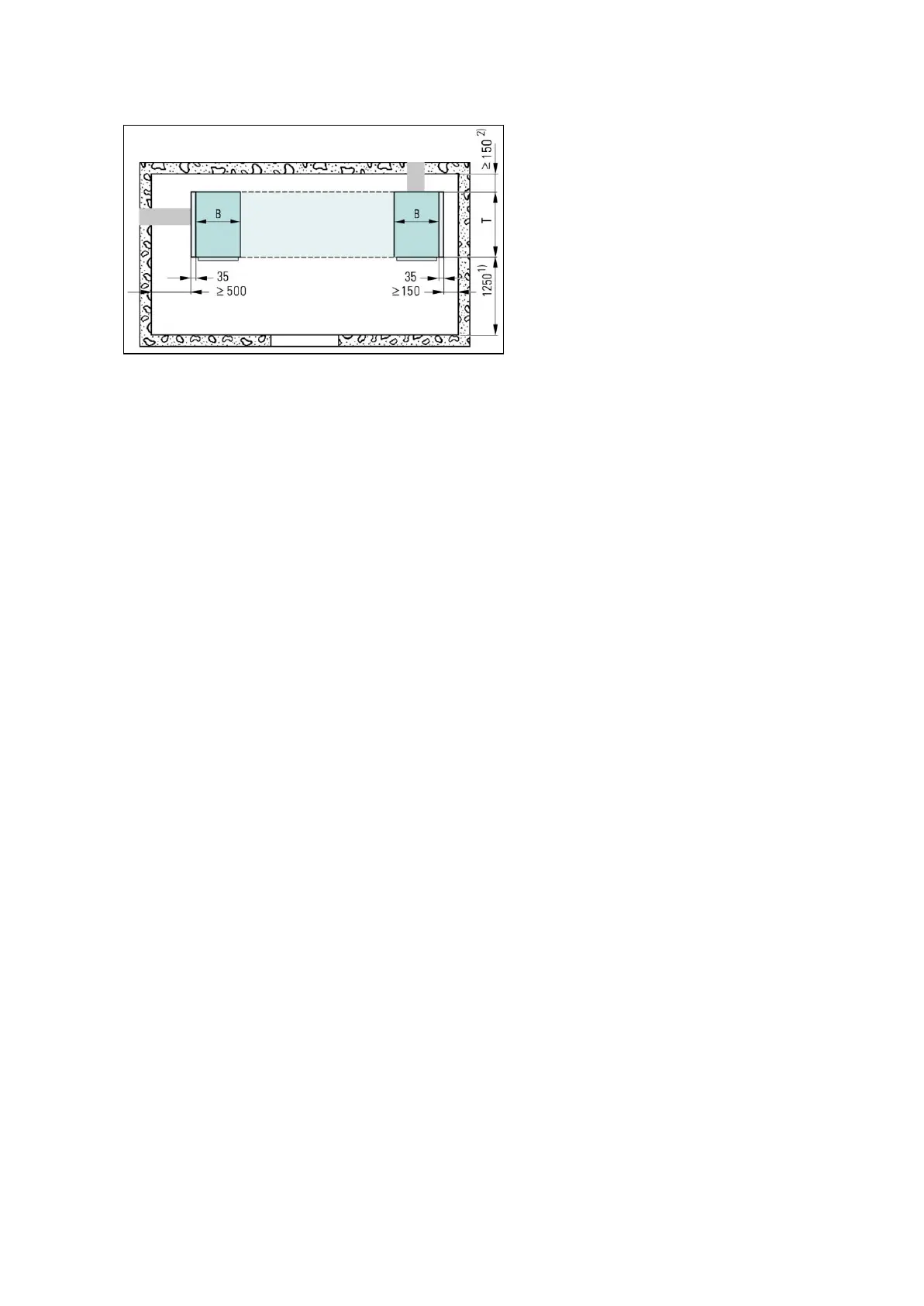
The evacuation duct must be implemented laterally or to the rear.
At least one panel of each busbar section (if bus sectionalizer available) must have one duct system connected
laterally or at the rear.
The length of the switchgear and the number of busbar components has no influence on the configuration of
the duct system.
Lateral evacuation duct:
The end panel (all available panel versions) used to adapt the evacuation duct must not contain any fittings for
busbar voltage transformers, busbar earthing switches or power supply bars/cables from above. Ventilated
panels are possible.
Evacuation duct to the rear:
The end panel used to adapt the evacuation duct must not contain any fittings for busbar voltage transformers,
busbar earthing switches or power supply bars/cables from above. Adaptation to an individual contactor panel
with panel width 435 mm is not possible, only in the middle between two contactor panels with panel
width 435 mm.

 Loading...


