Description
2.3 Protection system
3WA1 air circuit breaker
74 Equipment Manual, 02/2023, 92310000002-06
(2) The "DAS+ active" light should be installed in such a way that it is clearly visible to
maintenance personnel.
It is only active when all circuit breakers are in the maintenance mode DAS+. The
maximum switching and continuous current of the digital output ETU-OUT is 0.1 A at
24 V DC. A coupling relay must be used for higher loads or other voltages.
(3) 3WA air circuit breaker
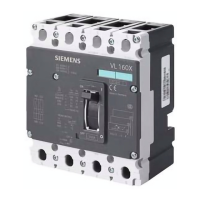
(4) 3VA6 molded case circuit breaker with Maintenance Mode Box MMB300
(5) On/off switch for activating the maintenance mode DAS+
The switch should be installed in a suitable position outside the arc-flash zone.
The DAS+ system is compatible with the 3WL circuit breaker with COM35. For more
information, refer to the "3WL air circuit breakers via COM35 - PROFINET IO, Modbus
TCP" Communication Manual; see Chapter Reference documents (Page 18).
DAS+ is not compatible with 3WL10 and 3VA27 circuit breakers.
Activation
The maintenance mode DAS+ can be activated in various ways.
Activation options:
• Digital ETU input of the circuit breaker, secondary disconnect terminals X8-5 and X8-
6.
Depending on the selected signal state (LOW/HIGH), the input can be controlled via
an NC contact or an NO contact.
• Operating key on the display of the ETU600 electronic trip unit
• Input of a digital input/output module
• Via the fieldbus interfaces of a communications module, see Chapter Communication
and system connection (Page 138).
• Via Bluetooth or the USB-C interface and the SENTRON powerconfig configuration
software.
The activated maintenance mode DAS+ is indicated by the blue LED on the electronic
trip unit and on the display.
A message can also be sent via the following signals:
• Digital ETU output of the circuit breaker, secondary disconnect terminal X8-7 and X8-
8
• Via an output of a digital input/output module
• Via fieldbus communication

 Loading...


