Description
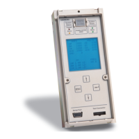
2.4 ETU300 electronic trip unit
3WA1 air circuit breaker
Equipment Manual, 02/2023, 92310000002-06
83
The following circuit diagram shows the integration of the digital input and output of the
ETU into a control and signaling system using the example of 2 circuit breakers.
Depending on the load, a coupling relay must be used at the output.
The example also shows the polarity-independent control of the input.
2.4.3.3 External current sensor
The neutral current can be measured with a current sensor. With a 3-pole circuit
breaker, the external current sensor for the N-conductor must be used for this purpose.
The external current sensor for the N-conductor (N-CT) is connected to secondary
disconnect terminals X8-9 and X8-10.
The external current sensors for the N-conductor are suitable for the ETU300 and
ETU600 electronic trip units and are described in Chapter External current sensor for
neutral pole (Page 349).
Note
The ETU300 electronic trip unit monitors the current sensors of the phases. If no
external current sensor for the N
-conductor is connected on a 3-pole circuit breaker,
secondary disconnect terminals X8
-9 and X8-10 must be terminated using terminating
resistor "L" which is included in the scope of supply of the circuit breaker. A wire ju
mper
-circuiting the input can also be used as an alternative.

 Loading...


