Readers
5.3 SIMATIC RF650R
SIMATIC RF600
System Manual, 11/2018, J31069-D0171-U001-A21-7618
121
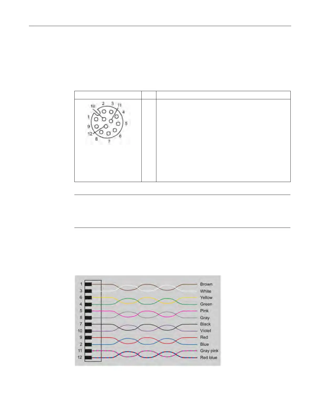
5.3.1.3 Pin assignment of the DI/DQ interface (X10 DI/DQ)
View of the DI/DQ interface (reader end)
Table 5- 16 Pin assignment of the DI/DQ interface
1
2
3
4
5
6
7
8
9
10
11
GND (output for supply of digital inputs/outputs [not electrical-
ly isolated])
VCC (output for supply of digital inputs/outputs [not electrically
isolated])
DO Common / Output Common
DO 0 / Output 00
DO 1 / Output 01
DO 2 / Output 02
DO 3 / Output 03
DI 0 / Input 00
DI Common / Input Common
DI 1 / Input 01
DI 2 / Input 02
Note
Requirement for external power sources
When the DI/DQ interface is supplied with power by an external power source, this source
mus
t meet the requirements for LPS (Limited Power Sources) and NEC Class 2.
Color scheme of the DI/DQ standard cable with M12 connector
The following figure shows the color scheme of the DI/DQ standard cable from Siemens
(6GT2891-0CH50). You can use the color scheme to assign the wire colors to the pins.
Figure 5-10 Wiring diagram: M12 connector