S7-1200 Functional Safety Manual
Manual, 02/2015, A5E03470344-AA
105
Fail-Safe signal module (SM) I/O configuration
All connected fail-safe SM I/O must have their operating properties configured by the
STEP 7 Safety configuration software. You have the responsibility to ensure that no
unconfigured SMs are connected in a fail-safe automation system.
Configuring fail-safe SM I/O properties
To configure fail-safe SM I/O properties, follow these steps:
1. Select "Device configuration" in the project tree.
2. Place fail-safe I/O devices into your project's "Device view".
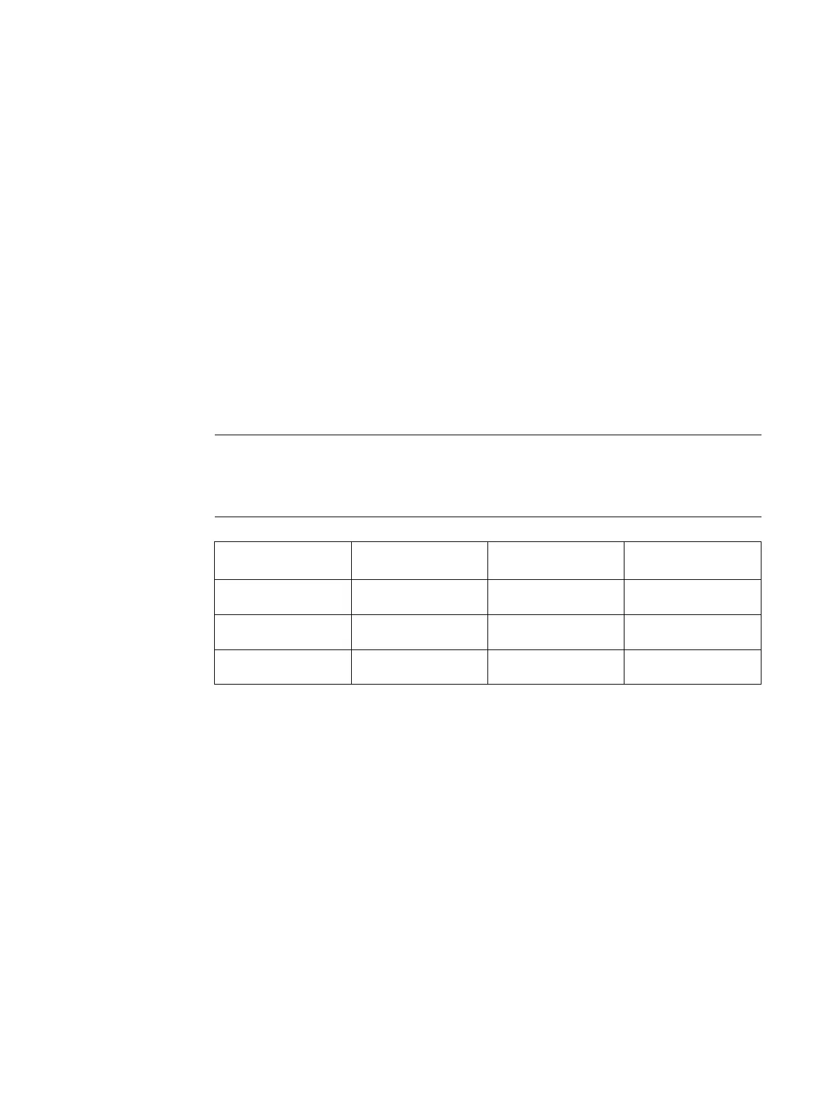
-safe SM's each use both I's and Q's, even though they may physically only have
input channels or only have output channels. The extra bytes carry safety status and data
integrity information.
Output (Q) bytes re-
quired
SM 1226 F-DI 16 x 24
8 - 16 (input) 9 5
SM 1226 F-DQ 4 x 24
4 (output) 6 6
SM 1226 F-DQ 2 x
Relay
2 (output) 6 6
3. Select the image of a fail-safe I/O device (on the Device view or Device overview) and
view the module's "Properties" tab.
4. On the
view, select the
tab.
5. Click on the module properties tree and expand the branches for an I/O module. You can
select a module (for example, "F-DI16") and see all the properties. You can also select a
module branch (for example, "F-parameters", "DI-parameters", or "Channel parameters")
and see a subset of the properties.
6. Select a property in the left-side property tree and then set values in the right-side
property fields.
7. A successful compile and download of your hardware configuration to an S7-1200 fail-
safe CPU automatically puts your new configuration settings in the I/O modules.

 Loading...


