Getting started
2.2 Configuring
S7-1200 Functional Safety Manual
Manual, 02/2015, A5E03470344-AA
35
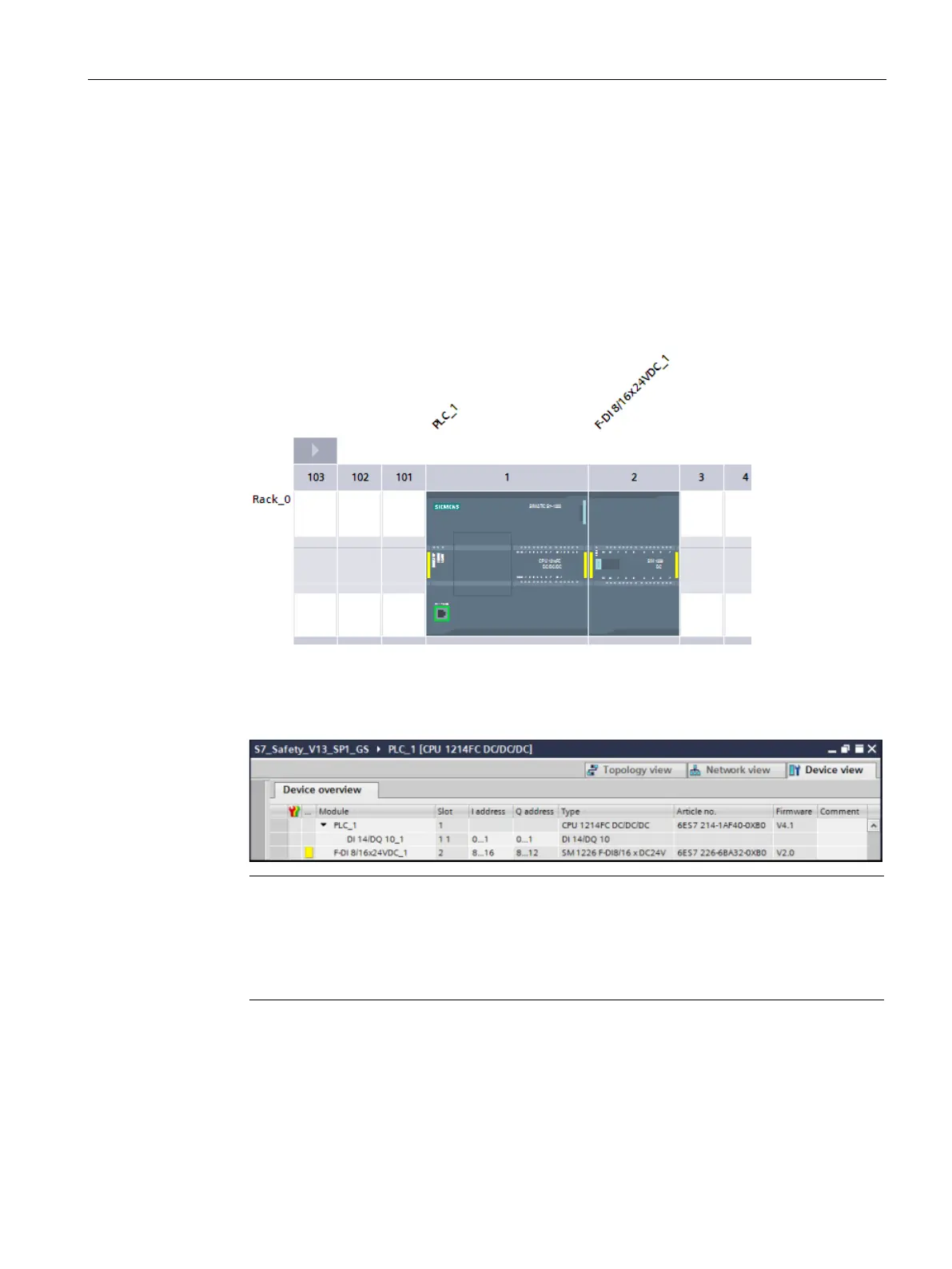
Step 3: Configuring an SM1226 F-DI 16 x 24 VDC for connecting an emergency
stop switch, position switches, and the laser scanner
In this step, you configure an F-DI for connecting an emergency stop switch, the position
switches for monitoring a safety door, and the laser scanner for monitoring the entry area.
1. In the Device View of the S7-1200, use drag-and-drop to add an F-DI 8/16x24VDC_1
digital electronic module from the hardware catalog to slot 2.
2. Open "Device data" to display the "Device overview" area. Here, you can change the
starting addresses for the inputs and outputs of your fail-safe module. Use the module
default I/O addresses of "8" and "8" for this example (inputs begin at byte 8, and outputs
begin at byte 8).
-safe SMs each use both Is and Qs, even though they may physically only have
input channels or only have output channels.
-DI can have 8 - 16 input channels; however, the SM requires 9 input (I) bytes and

 Loading...


