Fail-Safe CPU and signal module (SM) installation
4.1 S7-1200 Fail-Safe modules installation and removal
S7-1200 Functional Safety Manual
Manual, 02/2015, A5E03470344-AA
89
Removing and reinstalling the S7-1200 terminal block connector
CPUs, signal boards (SB) and signal modules (SM) have removable connectors to make
wiring easy.
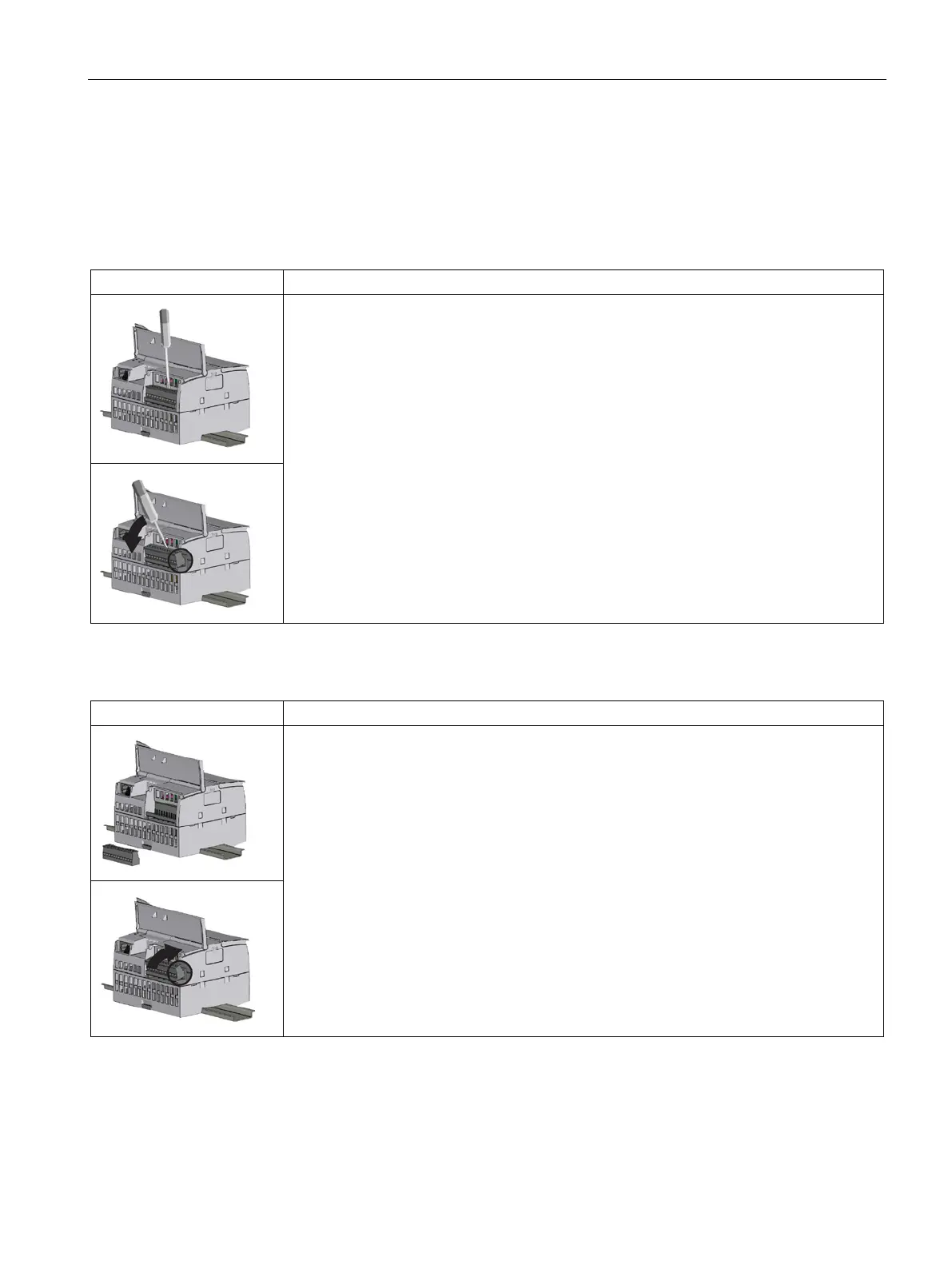
Table 4- 5 Removing terminal blocks (CPU example)
Prepare the system for terminal block connector removal by removing the power from the
CPU and opening the cover above the connector.
1. Ensure that the CPU and all S7-1200 equipment are disconnected from electrical power.
2. Inspect the top of the connector and locate the slot for the tip of the screwdriver.
3. Insert a screwdriver into the slot.
4. Gently pry the top of the connector away from the CPU. The connector releases with a
snap.
5. Grasp the connector and pull away from the CPU.
Table 4- 6 Installing the connector
Prepare the components for terminal block installation by removing power from the CPU and
opening the cover for connector.
1. Ensure that the CPU and all S7-1200 equipment are disconnected from electrical power.
2. Align the connector with the pins on the unit.
3. Align the wiring edge of the connector inside the rim of the connector base.
4. Press firmly down and rotate until the connector snaps into place.
Check carefully to ensure that the connector is properly aligned and fully engaged.

 Loading...


