Technical specifications
A.2 Fail-Safe CPU technical specifications
S7-1200 Functional Safety Manual
168 Manual, 02/2015, A5E03470344-AA
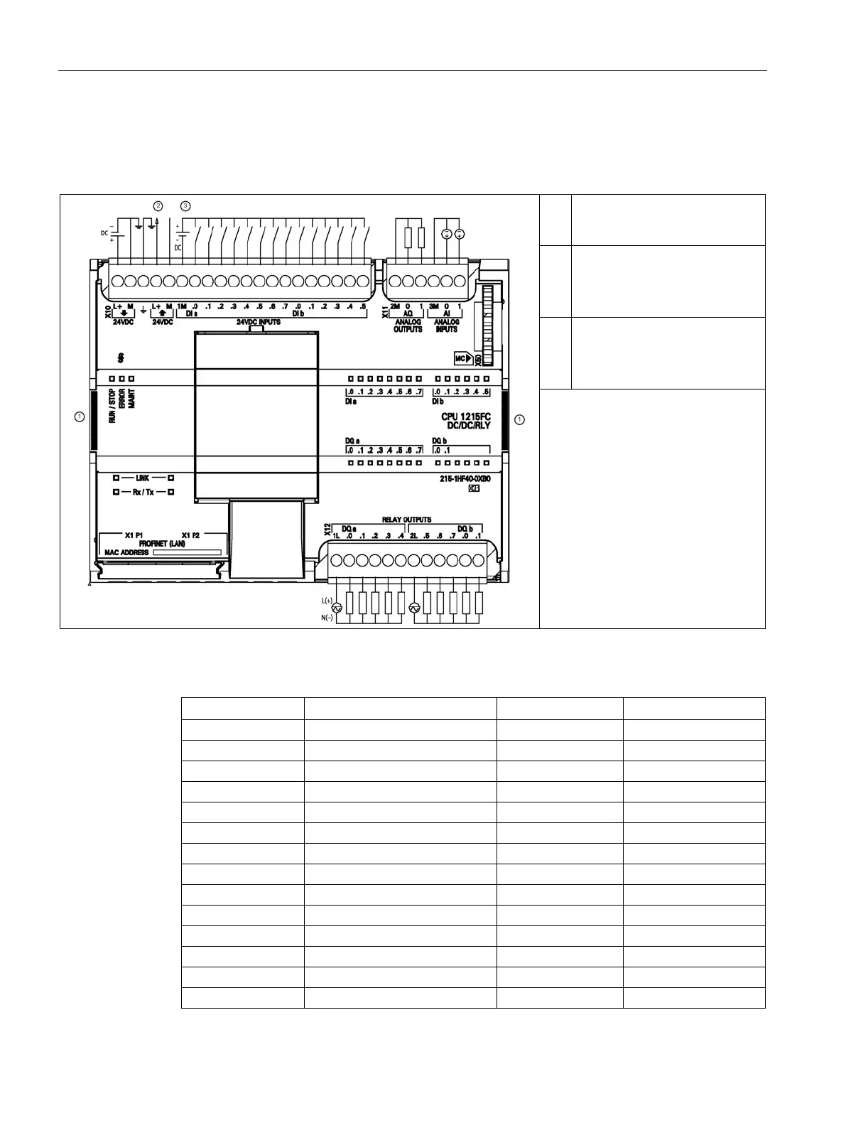
CPU 1215FC wiring diagrams
Table A- 41 CPU 1215FC DC/DC/Relay (6ES7 215-1HF40-0XB0)
The two rectangular areas are
yellow. These are only on the
fail-safe CPUs.
②
24 VDC Sensor Power Out
For additional noise immunity,
connect "M" to chassis ground
even if not using sensor supply.
③
For sinking inputs, connect "-" to
"M" (shown).
For sourcing inputs, connect "+"
Note: X11 connectors must be gold.
See Appendix B, Spare Parts for
article number.
Table A- 42 Connector pin locations for CPU 1215FC DC/DC/Relay (6ES7 215-1HF40-0XB0)
1 L+ / 24VDC 2M 1L

 Loading...


