Fail-Safe CPU and signal module (SM) installation
4.2 Fail-Safe system electrical design rules
S7-1200 Functional Safety Manual
94 Manual, 02/2015, A5E03470344-AA
Calculating a sample power requirement
CPU power budget calculation for example system
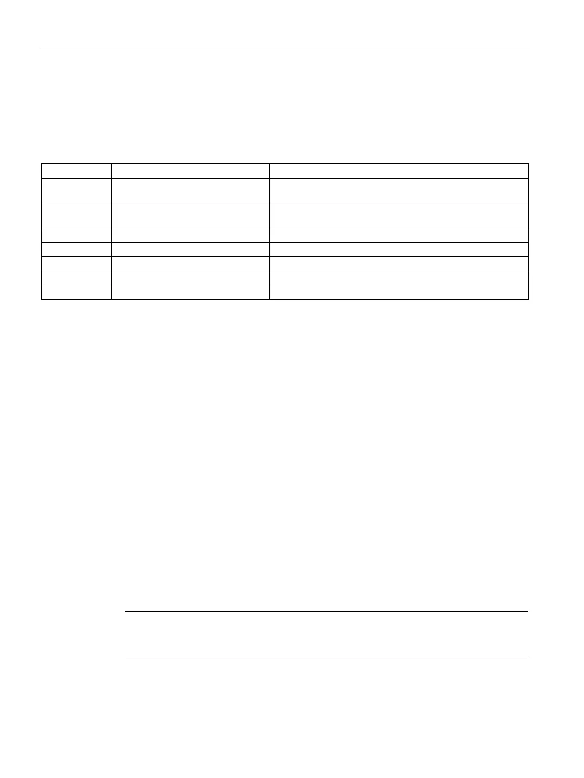
The following example shows the power requirements for a system that includes:
1 CPU 1214FC DC/DC/Relay Fail-safe CPU with 14 standard (not fail-safe) digital inputs and
10 standard (not fail-safe) digital outputs
1 SB 1223 2 x 24 VDC Input/ 2 x 24
VDC Output
Standard I/O signal board with 2 digital inputs
Fail-safe signal module with 16 digital inputs
Fail-safe signal module with 4 digital outputs
Fail-safe signal module with 2 relay outputs
SM 1223 8 DC In/8 Relay Out
Standard signal module with 8 digital inputs and 8 relay outputs
This example system uses a total of 56 inputs and 40 outputs with a mix of standard and fail-
safe I/O. If a digital input channel is disconnected and not used, then that input is excluded
from the power calculation.
The current supply and consumption numbers are obtained from each module's technical
specifications.
The example budget shows inadequate 24VDC CPU power
An external 24 VDC power supply is necessary to supply a fail-safe CPU's L+ and M input
terminals (with the arrow symbol pointing into the CPU). In the example, fail-safe SM 24
VDC loads are also connected to the external power supply. Other devices in your system
may connect to the external 24 VDC supply. You must ensure that the external supply has
sufficient power available. A total external power load calculation is not described in the
example. The purpose of the example is to verify sufficient power is available for loads that
are supplied directly from the CPU.
The fail-safe CPU in this example provides sufficient 5 VDC current for all add-on modules,
but insufficient 24 VDC current for all of the standard digital inputs and outputs. The fail-safe
SMs connect to a 24 VDC external supply which moves their 24 VDC loads off of the CPU
power budget calculation.
The example system requires 424 mA at 24 VDC from the fail-safe CPU, but the CPU can
provide only 400 mA. This result requires moving at least 24 mA of the 24 VDC CPU load, to
the external 24 VDC power supply. A solution would be to move the 24 VDC power
connections for the 24 standard relay outputs, from the CPU to the external power supply.
This action would reduce the CPU 24 VDC load by 264 mA.
Note
The power required to drive the fail
-safe CPU's internal relay coils is already allocated. Do
not include the internal relay power requirements in a power budget calculation.

 Loading...


