Fail-Safe CPU and signal module (SM) installation
4.2 Fail-Safe system electrical design rules
S7-1200 Functional Safety Manual
Manual, 02/2015, A5E03470344-AA
95
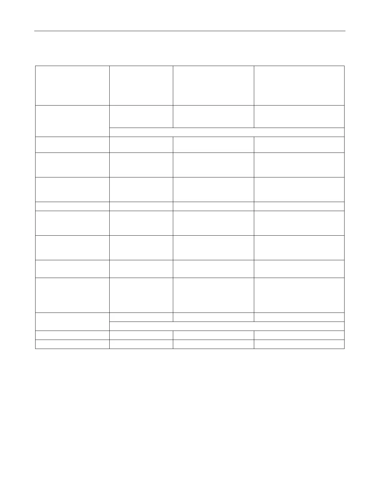
Table 4- 7 Sample power budget
5 VDC distributed by
internal bus when
modules are installed
24 VDC distributed by connec-
tion to fail-safe CPU terminals
L+ and M, (identified by arrow
pointing away from the fail-
safe CPU)
24 VDC supplied by connection to
external power supply (separate
external supply power budget
required)
CPU 1214FC DC/DC/Relay
maximum output current
1600 mA 400 mA Obtain maximum current rating
from the external power supply
Minus
24 VDC external power supply
loads
CPU 1214FC, 14 X 24 VDC
14 standard inputs located on
the CPU:
1 SB 1223, 2 X 24 VDC 50 mA 2 standard inputs located on a
signal board:
1 SM 1226 F-DI 16 x 24
VDC
155 mA Module plus 16 fail-safe inputs (8
paired channels):
130 mA + 16 * 6 mA = 226 mA
1 SM 1226 F-DQ 4X 24
VDC
125 mA
4 fail-safe digital outputs:
170 mA + load current for all 4 P-
switches + Vs1/Vs2 load current
1 SM 1226 F-DQ 2 X relay 120 mA 2 fail-safe relay outputs:
3 SM 1223 DI 8 x 24 VDC,
DQ 8 x Relay
3 * 145 mA = 435 mA 24 standard digital inputs:
3 * 8 * 4 mA = 96 mA
24 standard relay outputs:

 Loading...


