S7-1200 Functional Safety Manual
Manual, 02/2015, A5E03470344-AA
193
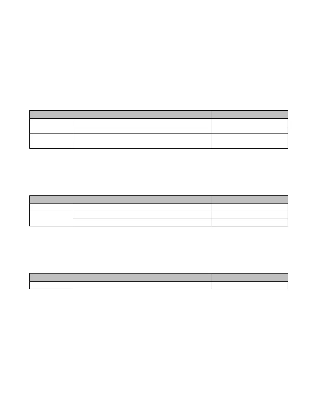
Table B- 1 Fail-Safe CPUs
CPU 1214FC
CPU 1215FC CPU 1215FC DC/DC/DC 6ES7 215-1AF40-0XB0
Fail-Safe signal modules (SM)
Table B- 2 Fail-Safe signal modules (SM)
Digital output
Table B- 3 Companion products

 Loading...


