Technical specifications
A.3 Fail-Safe signal module (SM) technical specifications
S7-1200 Functional Safety Manual
172 Manual, 02/2015, A5E03470344-AA
The SM 1226 F-DI 16 x 24 VDC user data space is 2 bytes (16 bits) of process value input
followed by 2 bytes of quality bits.
This is the bit structure for an F-DI configured with input start address 8:
DI b.7 I9.7 I11.7
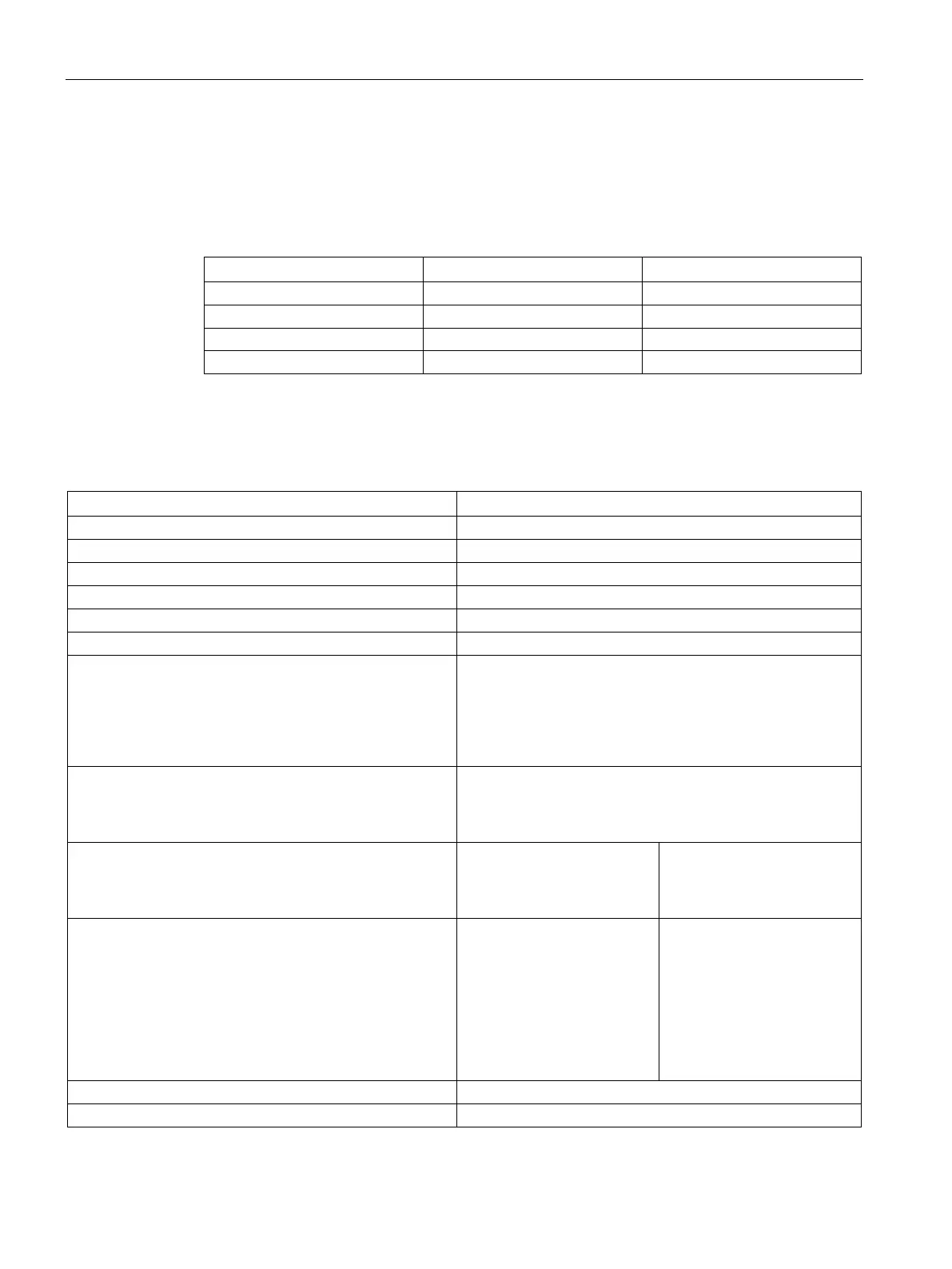
Table A- 46 General specifications
Dimensions W x H x D (mm)
Current consumption (SM Bus, 5 VDC)
Current consumption (24 VDC)
130 mA + 6 mA / input used + any Vs1/Vs2 current used
Isolation
• Signal terminals on this module are referenced to this
module's M terminal and NOT ISOLATED from each oth-
er.
• Signal terminals on this module are isolated to 500VAC
for 1 min from S7-1200 system internal logic and Ground.
Assigned address area:
• I/O area for inputs
• I/O area for outputs
9 bytes
5 bytes
Maximum achievable safety class:
• In accordance with IEC 61508:2010
• In accordance with EN ISO 13849-1:2008
1-channel
SIL 2
Category 3, PL d
2-channel
SIL 3
Category 4, PL e
Fail-safe performance characteristics:
• Operation in Low Demand Mode (Average probability
of a dangerous failure on demand), PFD_avg
• Operation in High Demand or Continuous Mode (Aver-
age frequency of a dangerous failure per hour), PFH
• Proof test interval (Mission time or Useful lifetime)
• Safety repair time
SIL 2
5e-4
1e-8
20 years
100 hours
SIL 3
1e-5
1e-10
20 years
100 hours

 Loading...


