Technical specifications
A.3 Fail-Safe signal module (SM) technical specifications
S7-1200 Functional Safety Manual
Manual, 02/2015, A5E03470344-AA
175
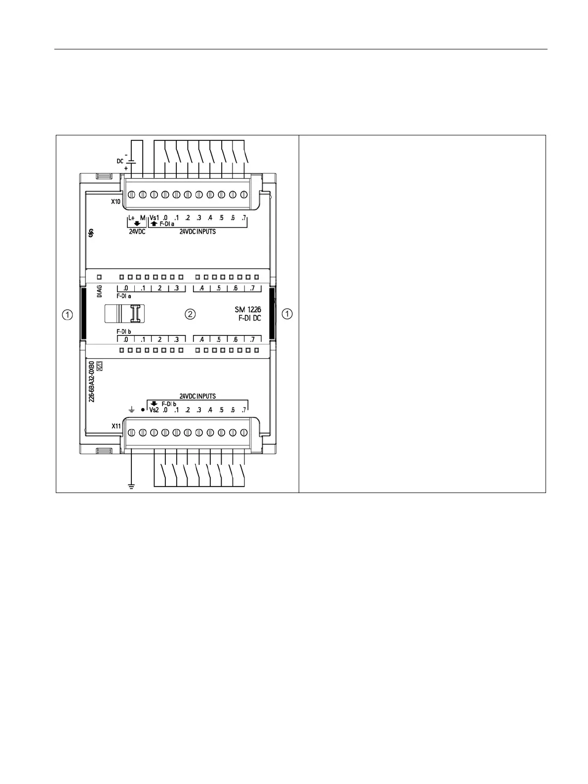
Table A- 51 SM 1226 F-DI 16 x 24 VDC (6ES7 226-6BA32-0XB0)
The two rectangular areas are yellow. These are only on
the fail-safe signal modules.
② Two LEDs per input:
• One for channel status: Green (on = input on, off = input
off)
• One for channel faults: Red (on = problem/passivated, off
= ok, blink = ready to reintegrate (activate))
Note: Refer to "Digital input applications" (Page 68) for alter-
nate applications wiring.

 Loading...


