Technical specifications
A.3 Fail-Safe signal module (SM) technical specifications
S7-1200 Functional Safety Manual
174 Manual, 02/2015, A5E03470344-AA
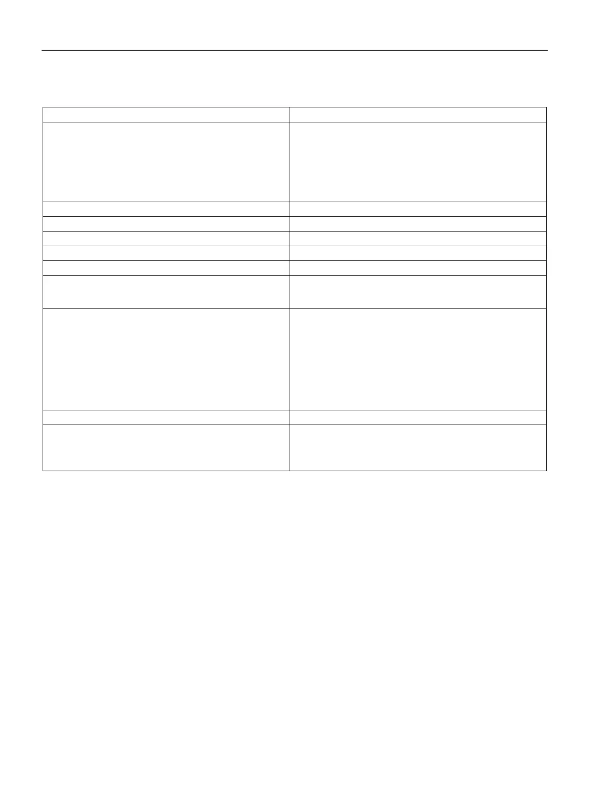
Table A- 50 Digital inputs
Number of inputs:
• 1oo1 evaluation
• 1oo2 evaluation
16 maximum
8 maximum
Note: You can individually assign each pair of inputs "a.x"
and "b.x" as a single 1oo2 channel or as 2 separate 1oo1
Sink (IEC 61131-2 Type 1)
15 VDC at 3 mA to 30 VDC at 6 mA
Connection of 2-wire proximity switch (BERO):
• Permissible quiescent current
Not possible
0.5 mA maximum
Filter times
• 0.8 ms
• 1.6 ms
• 3.2 ms
• 6.4 ms
• 12.8 ms
Note: Refer to "Fail-Safe signal module (SM) response times"
(Page 197) for further information.
Number of inputs on simultaneously
16 inputs at 55 °C horizontal or 45 °C vertical
Cable length (meters)
1
• 200 m unshielded with input filter time of 1.6 ms to 12.6
ms
• 200 m shielded with input filter time of 0.8 ms to 12.6 s
1
1
With an input delay of 0.8 ms, shielded cables must be used for the digital inputs and the sensor supply.

 Loading...


