Fail-Safe signal module (SM) I/O configuration
5.3 Configuring SM 1226 F-DI 16 x 24 VDC DI and channel parameters
S7-1200 Functional Safety Manual
Manual, 02/2015, A5E03470344-AA
107
Configuring SM 1226 F-DI 16 x 24 VDC DI and channel parameters
Table 5- 2 SM 1226 F-DI 16 x 24 VDC DI parameters
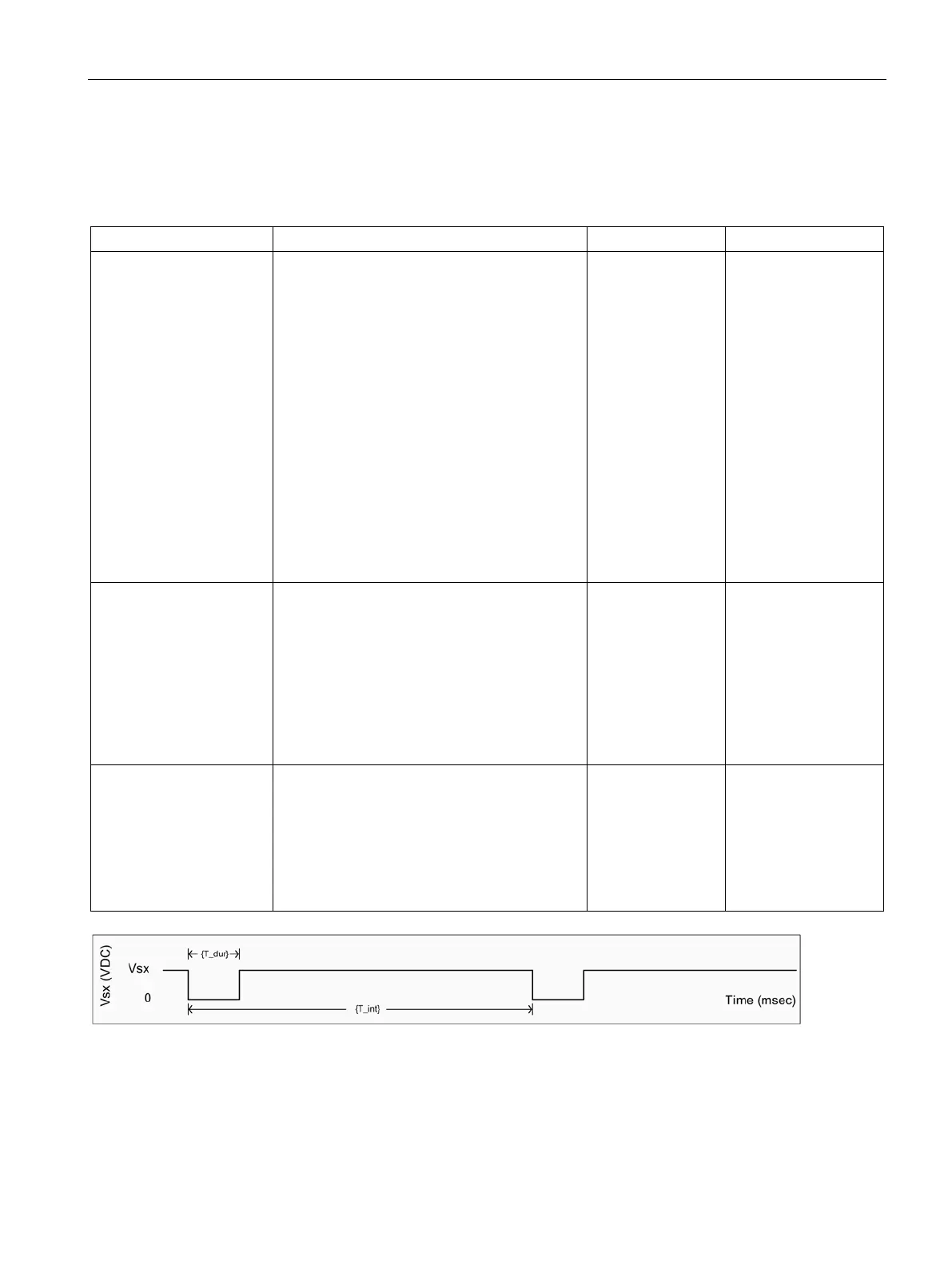
Short-circuit test This test creates short duration OFF pulses on
the sensor power supplies. Input circuits pow-
ered by Vs1 and Vs2 are expected to be OFF
during the sensor OFF time. Failure to detect
OFF when a sensor supply is OFF indicates a
short-circuit to a power source or another fault
that prevents the input from properly detecting
a "0". Input channels which fail this test are
passivated.
During the test, the reported process value will
not change, so the configured "Duration of
short-circuit test" increases the response time.
An actual process "0" occuring near the begin-
ning of a test will not be reported to the user
program until after the "Duration of short-circuit
test" time has elapsed.
The check box must be selected to activate the
Check box dese-
lected
Check box:
• Selected
• Deselected
Interval for short-circuit
test (see T_int in figure
below)
This value is the time between the OFF pulses
of the sensor supply.
Refer to the figure below for further information.
Note: The interval must be a minimum of eight
times the duration.
25.6 ms
• 12.8 ms
• 25.6 ms
• 51.2 ms
• 102.4 ms
• 204.8 ms
• 409.6 ms
• 819.2 ms
Duration of short-circuit
test (see T_dur in figure
below)
This value is the time that the power supply
remains off during the test. The short-circuit
test OFF pulse must be long enough for the
external sensors and wiring to respond and
present a "0" to the inputs.
Refer to the figure below for further information.
Note: The interval must be a minimum of eight
1.6 ms
• 1.6 ms
• 3.2 ms
• 6.4 ms
• 12.8 ms
Vs1 or Vs2 sensor supplies (VDC)
Short-circuit test interval (time period) between the OFF pulses of the sensor supply
Short-circuit test OFF pulse time duration (msec)

 Loading...


