Product overview
1.4 S7-1200 Fail-Safe signal modules (SM)
S7-1200 Functional Safety Manual
20 Manual, 02/2015, A5E03470344-AA
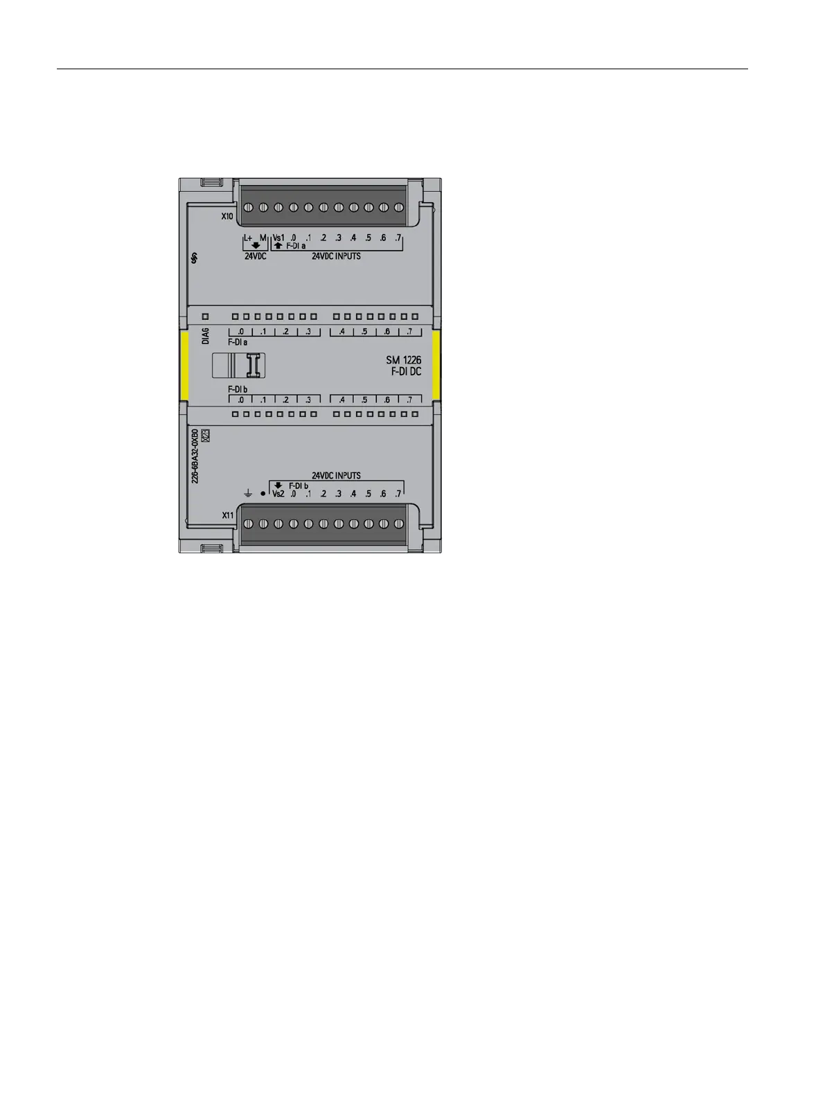
-DI 16 x 24 VDC is an S7-
1200 signal module (SM) for use in fail
-safe
applications. The inputs are rated for
connec-
DC sensors/switches and 3/4-wire
proximity switches (for example, BEROs:
Siemens line of no
-touch sensors) and have
-2 type 1 input rating.
The module has two sensor supply outputs
that can each power eight external sensors
(inp
uts).
The F-DI consists of 16 input channels (F-DI a.0..a.7, F-DI b.0...b.7). You can configure
these inputs as sixteen one-out-of-one (1oo1) inputs (SIL 2/Category 3/PL d), eight one-out-
of-two (1oo2) inputs (SIL 3/Category 3 or Category 4/PL e), or combinations of 1oo1 and
1oo2 channels. One microcomputer monitors inputs a.0 to a.7, and the other microcomputer
monitors inputs b.0 to b.7. The corresponding channels from a and b (a.0, b.0), (a.1,
b.1)...(a.7,b.7) form a 1oo2 channel group . The "a" input, the first of the two inputs, conveys
the signal in a 1oo2 configuration. For example, if you wire I8.0 and I9.0 in a 1oo2
configuration and configure STEP 7 to use 1oo2 sensor evaluation, the signal appears at
only the I8.0 input when you close or open the circuit for both.
When you configure a channel group as 1oo2, the two controllers must sense the same input
change within a configured time. Otherwise, the two controllers detect a discrepancy error.
The F-DI reports the 1oo2 input back to the fail-safe CPU as a single input.
If you use a sensor supply output to provide power to a sensor, you can enable short-circuit
testing. The short-circuit test checks for shorts to plus voltage by periodically pulsing the
sensor output off and verifying that the associated input is off. This short-circuit test also
checks for shorts to the other circuit in a 1oo2 paired input because the test pulses the two
sensor outputs off at different times. The short-circuit test does not detect shorts between
inputs in the same sensor group.
The processors cooperate in providing internal test pulses to each others process input
circuits, after the initial field interface, to verify that sensing electronics are responsive to "1"
and "0" inputs.

 Loading...


