Technical specifications
A.2 Fail-Safe CPU technical specifications
S7-1200 Functional Safety Manual
Manual, 02/2015, A5E03470344-AA
153
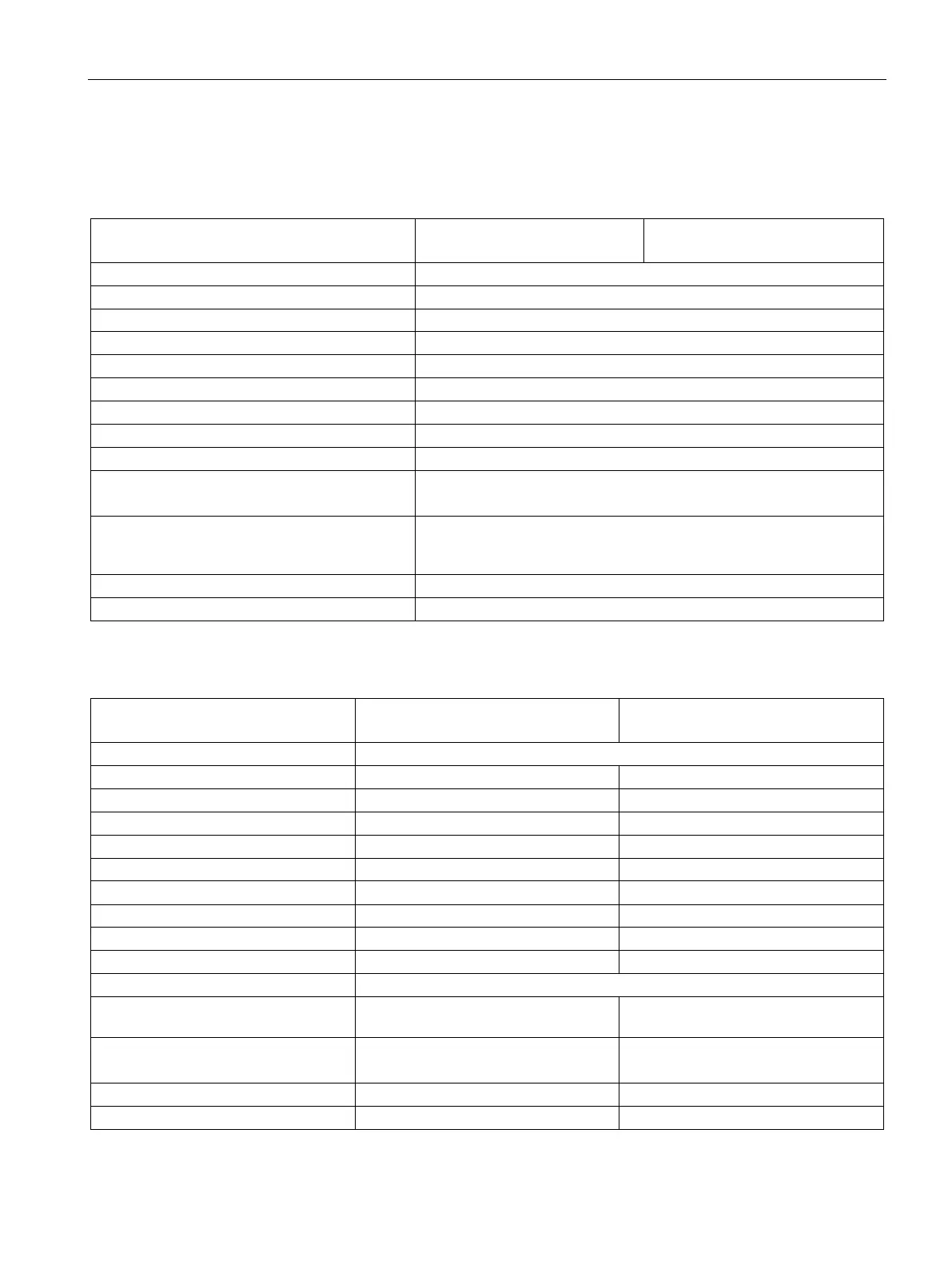
Digital inputs and outputs
Table A- 16 Digital inputs
Sink/Source (IEC Type 1 sink)
Continuous permissible voltage 30 VDC, max.
Logic 1 signal (min.) 15 VDC at 2.5 mA
Isolation (field side to logic)
Filter times us settings: 0.1, 0.2, 0.4, 0.8, 1.6, 3.2, 6.4, 10.0, 12.8, 20.0
ms settings: 0.05, 0.1, 0.2, 0.4, 0.8, 1.6, 3.2, 6.4, 10.0, 12.8, 20.0
HSC clock input rates (max.)
(Logic 1 Level = 15 to 26 VDC)
100/80 kHz (Ia.0 to Ia.5)
30/20 kHz (Ia.6 to Ib.5)
Number of inputs on simultaneously
14 inputs at 55 °C horizontal or 45 °C vertical
500 m shielded, 300 m unshielded, 50 m shielded for HSC inputs
Table A- 17 Digital outputs
Solid state - MOSFET (sourcing)
5 to 30 VDC or 5 to 250 VAC
Logic 1 signal at max. current
Logic 0 signal with 10 KΩ load
ON state resistance 0.2 Ω max. when new 0.6 Ω max.
Leakage current per point
Surge current 7 A with contacts closed 8 A for 100 ms max.
Required external overload protection
4
10 A maximum must be limited to any
5 A maximum must be limited to any
Isolation (field side to logic) 1500 VAC for 1 minute (coil to contact)
500 VAC for 1 minute
Isolation between open contacts

 Loading...


