Getting started
2.2 Configuring
S7-1200 Functional Safety Manual
34 Manual, 02/2015, A5E03470344-AA
Step 2: Configuring fail-safe CPU standard digital inputs for user
acknowledgement, feedback circuit, and start pushbutton
In this step, you assign parameters of fail-safe CPU standard digital inputs for the non-fail-
safe signals (user acknowledgement, feedback loop, and start pushbutton).
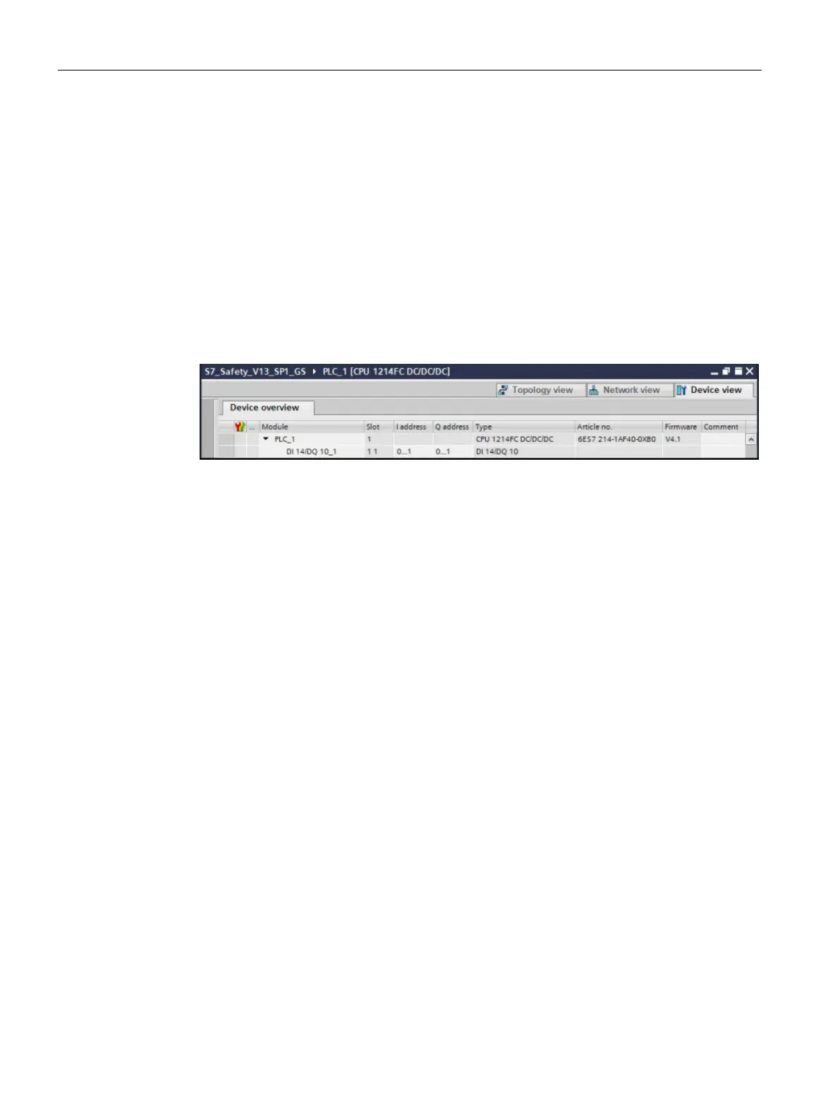
1. Assign the input address of the fail-safe CPU standard digital inputs to "0" for this
example. Assign the output address of the fail-safe CPU standard digital outputs to "0" as
well. You can assign these addresses in the CPU device configuration under "DI 14/DQ
10", "I/O addresses".
Refer to the "CPU 1214FC Device view" information from the TIA Portal shown below:
The configuration of the fail-safe CPU standard digital inputs is now complete.

 Loading...


