Fail-Safe CPU and signal module (SM) installation
4.1 S7-1200 Fail-Safe modules installation and removal
S7-1200 Functional Safety Manual
88 Manual, 02/2015, A5E03470344-AA
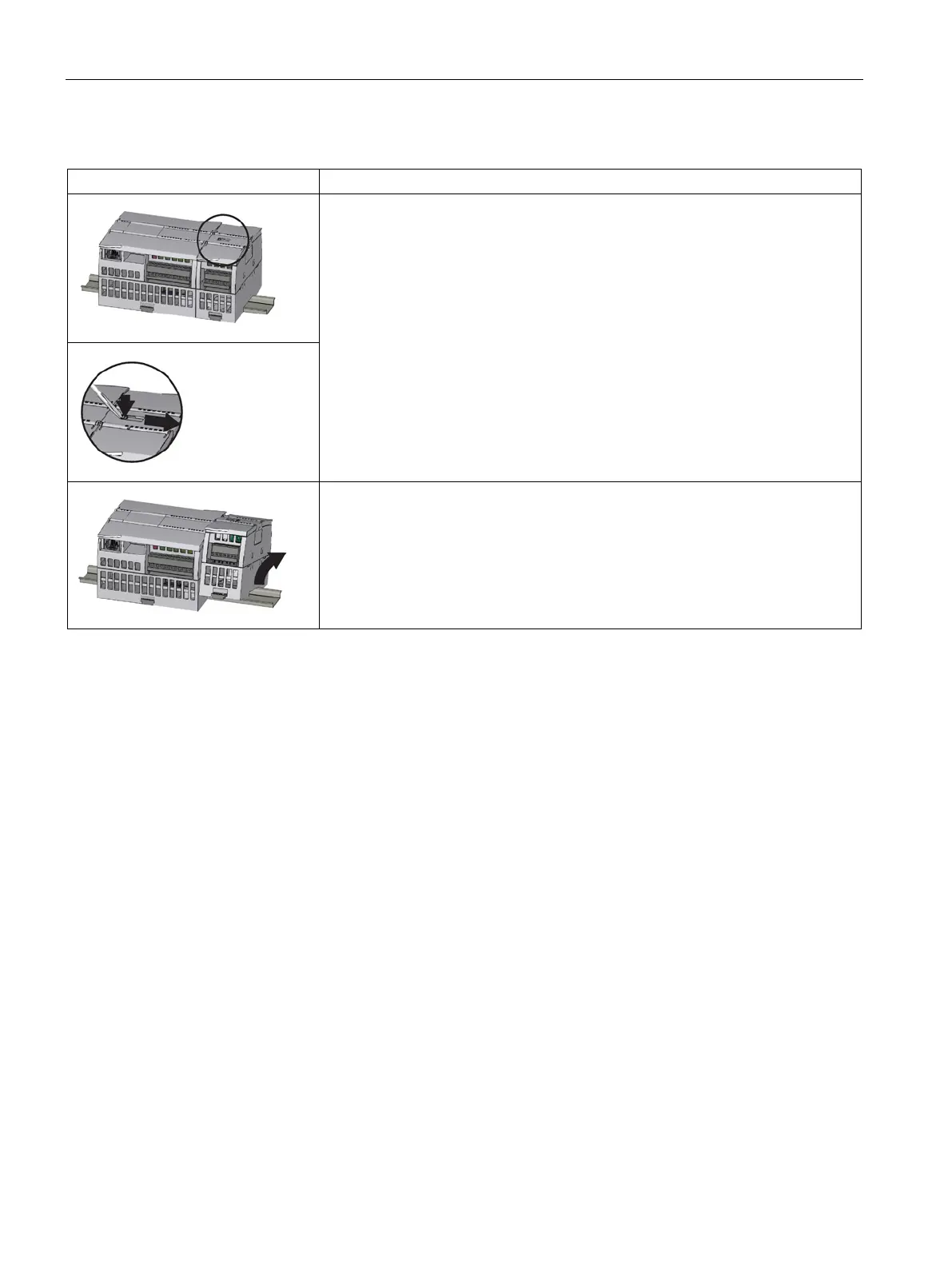
Table 4- 4 Removing an SM
You can remove any SM without removing the CPU or other SMs in place.
1. Ensure that the CPU and all S7-1200 equipment are disconnected from electri-
cal power.
2. Remove the I/O connectors and wiring from the SM. Refer to the terminal block
removal instructions (Page 89).
3. Retract the bus connector.
– Place a screwdriver beside the tab on the top of the SM.
– Press down to disengage the connector from the CPU.
– Slide the tab fully to the right.
When another SM is connected on the right, repeat this procedure for that SM.
Remove the SM:
1. Pull out the bottom DIN rail clip to release the SM from the rail.
2. Rotate the SM up and off the rail. Remove the SM from the system.
3. If required, cover the bus connector on the CPU to avoid contamination.
Follow the same procedure to remove a signal module from a signal module.

 Loading...


