Technical specifications
A.3 Fail-Safe signal module (SM) technical specifications
S7-1200 Functional Safety Manual
182 Manual, 02/2015, A5E03470344-AA
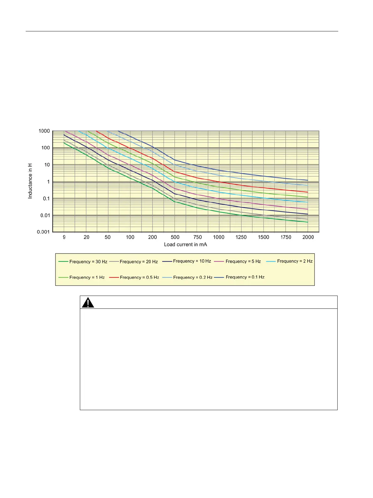
Switching of inductive loads
The graph below shows the maximum permitted inductive load and switching frequency
allowed using only the internal suppression circuits of the F-DQ DC outputs. You should
equip larger or more frequently switched inductive loads with external suppression circuits to
avoid early failure of the F-DQ DC output switch. The external suppression must conduct the
load current at a voltage less than the internal suppression threshold to avoid overloading
the internal suppression. Refer to "Guidelines for inductive loads" (Page 101) for more
information:
Unsuppressed inductive loads can lead to failures.
The following failures can result:
• Unsuppressed inductive loads can lead to early "stuck-on'" failures of F-DQ DC and F-
RLY outputs.
• Unsuppressed inductive load switching generates an EMI hazard to the PLC system
and correct processing of the safety function.
Death or serious personal injury and damage to machines and equipment may result if
proper precautions are not taken.
You should use suppressor circuits with inductive loads to limit the voltage rise when a
control output turns off and to limit the electrical noise generated when switching inductive
loads.

 Loading...


