Installation
2–13
IP244
C79000–B8576–C859–02
No load supply must be connected to pin number 20. The connection is used to supply
the contact on pin 1. The lines from pins 21 to 37 of the S5Ć115 must be connected to
0V (MĆbar) i.e. reference potential, using the appropriate adapter casing.
Depending on the configuration of the controller as a 2 or 3-step controller, the 17 digital outputs
are assigned consecutively. The maximum number of controllers is determined by the required
number of digital outputs (maximum 17).
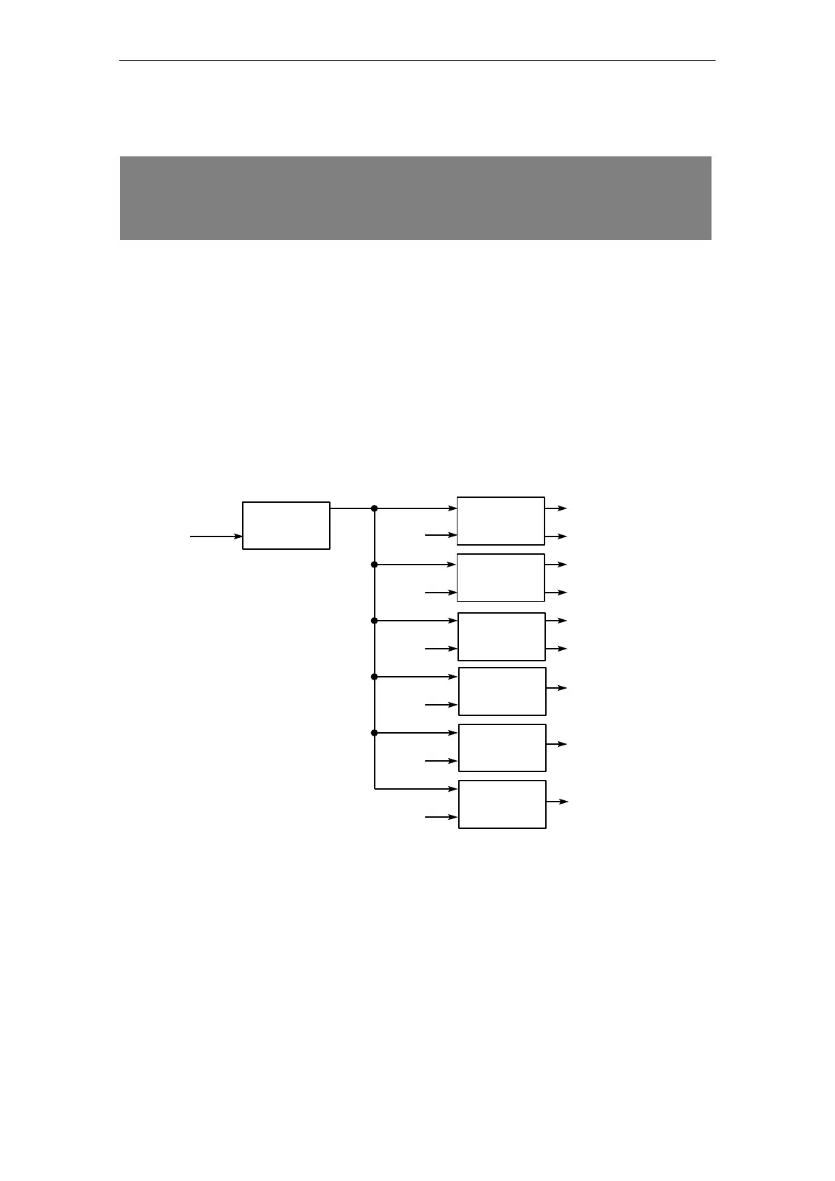
Example of controller configuration
You require cascaded control with controllers 1, 2 and 3 as 3-step controllers and controllers
4, 5 and 6 as 2-step controllers, all other controllers are disabled.
The assignments of inputs and outputs is shown in the following diagram:
DQ 11
DQ 8
Analog input
AI 0
AI 3
AI 5
AI 6
AI 2
AI 4
AI 1
DQ 10
DQ 12
DQ 13
DQ 14
DQ 15
DQ 16
DQ 9
Controller 0 is master controller
Heating
Cooling
controller
1
controller
2
controller
3
controller
4
controller
5
controller
6
controller
0
Cooling
Cooling
Heating
Heating
Heating
Heating
Heating
The remaining analog inputs are used only for measured value acquisition, the remaining digital
outputs are not used.