IP244
C79000–B8576–C866–01
7–25
Hardware Requirements
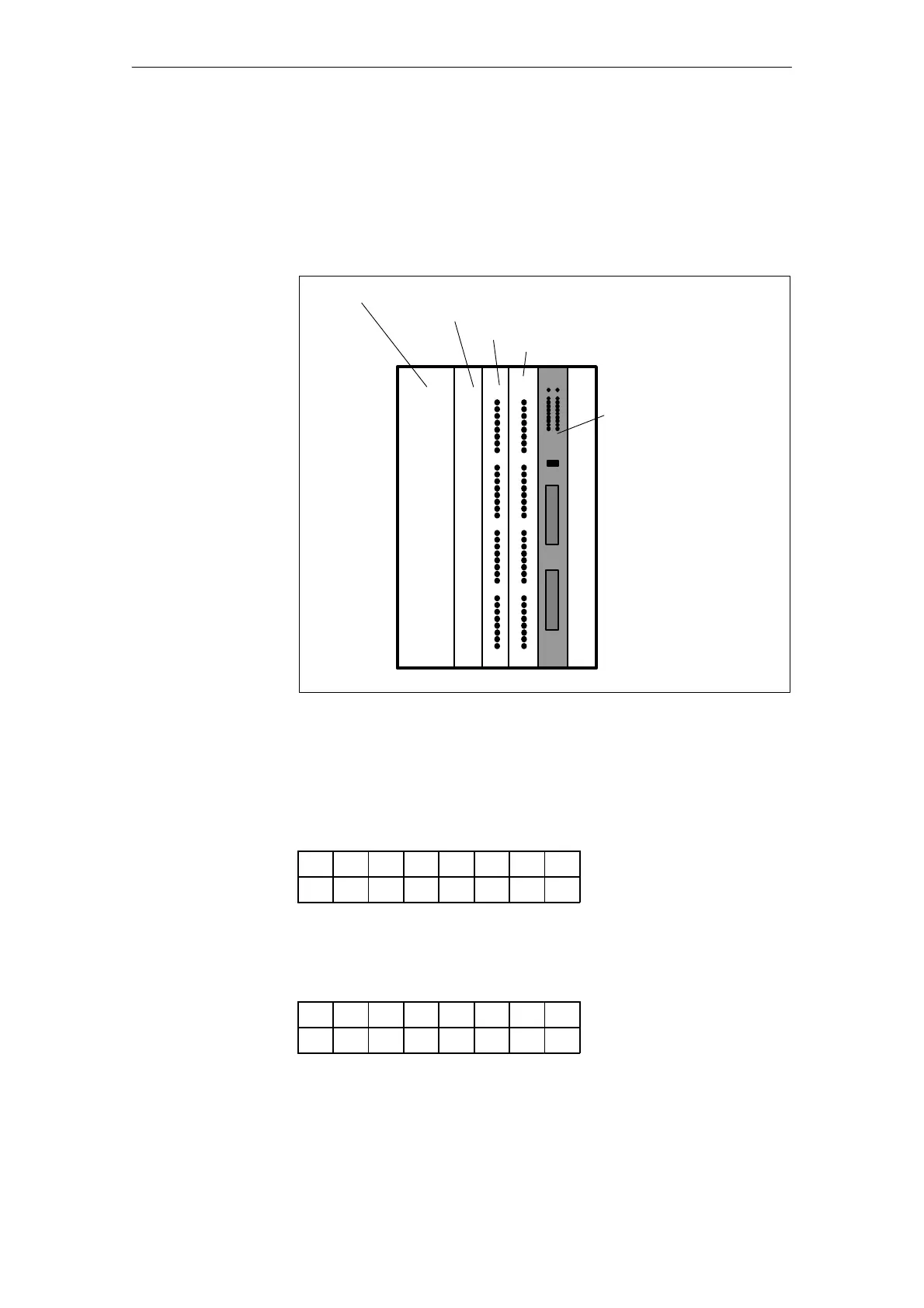
The example is based on the hardware shown in Fig. 2-1. It executes on any
equivalent hardware basis.
Power supply
unit
CPU 416-1
Input module
IP 244
in the adapter casing
Output module
Bild 2-1 Hardware structure required for the programming example
The module has been set to address ’0’ in the P area.
Address switch A76 (D = depressed):
87654321
off
on
Address switch A77 (D = depressed):
87654321
off
on
Introduction
Settings on the
IP 244 module
FC162