Technical Description
IP244B
C79000–B8576–C865–01
3–6
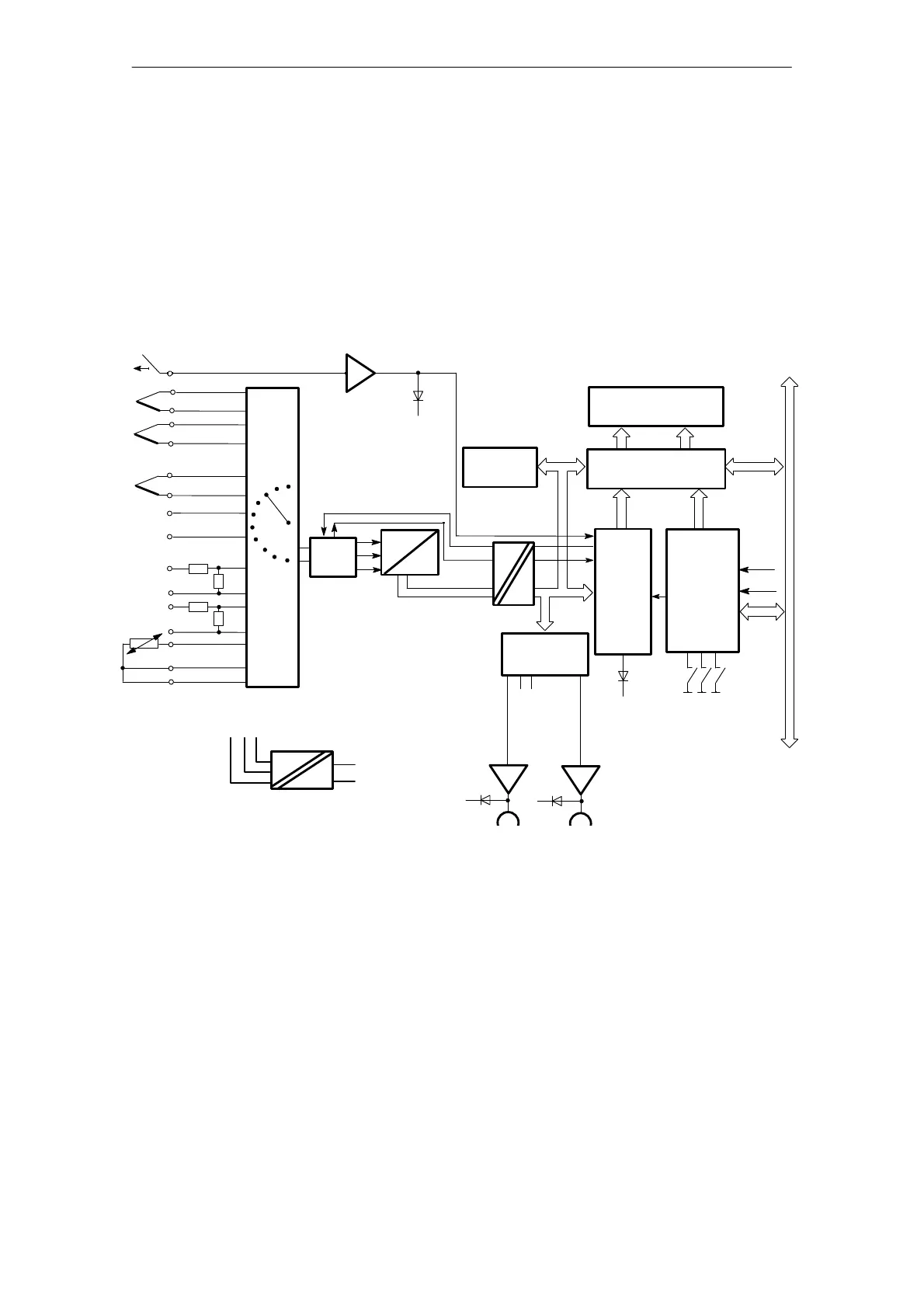
The microprocessor (P) processes the different functions of the controller module:
– Measuring values at a high common-mode range
– Measuring values via multiplexer and ADC
– Processing measured values according to the control algorithm (calculating system deviation
and manipulated variable, self-optimization)
– Monitoring values for alarm limits and generating alarms
– Outputting manipulated variables via registers and output driver stages
– Computing the temperature compensation values according to the reference junction tem-
perature (Pt 100)
– Controlling the interface to the S5 system bus
5Ćbit
subĆaddresses
0
Channel no.
LED
(E)
15
1
7
Pt 100
Digital input Contzrol ON/OFF
L +
LED 1
R/W
13
BASP
Module address
8
14
LED
(R)
Analog signal
routing;
open wire
detecton
internal data bus
Output
drivers
OptoĆcoupled
multiplexer
Address
8/12Ćbit
address
+PESP
A
D
Register
17 Bit
P
Interface
logic
Collision
control
LED 17
DA 1DA17
EPROM
RAM
8Ćbit
data
Data/address
selection
S5 bus
DC
DC
-+0
+5V
0V
Fig. 1.3/1 Block diagram of the temperature controller (IP 244 B-3AB31)
The module can be used as a switching two- or three-step controller with percentage output
according to the control algorithm in the EPROM.
The controller’s response (P, PI, PD, PID) is defined by parameters. 64 message frames of 32
bytes each are used for communication (setpoint values and parameters) between the CPU and
the temperature controller module.