Description of the Firmware
IP244
C79000–B8576–C860–02
4–14
The following errors are indicated for channels 13 and 14:
– positive tolerance exceeded,
– value below the negative tolerance.
A channel group error bit is generated for each individual controller or channel and a general group
error bit is generated in the function block for the module.
," +,)(#', #+ 1*( (* ," ",#'! +/#," #+ ( ,"* * '( +#!'%+ (* ,"
(**+)('#'! (',*(%%*
You have easy access to the following error messages via the function block:
Program monitoring (watchdog)
To monitor the correct execution of the program, the CPU interrogates a monitoring bit. This
bit changes its state once per second when the program is correctly executed (firmware
watchdog).
' **(* #+ )*+', #, #+ #'#, 0 ," #' ," -+* )*(!*& .# ," -',#(' %($
," +++ ," &(-% ,(( ( ,' ' #',* *+ /#," ," #',*'% ,#&#'! ,"#+ #+
+#!'%% .# ," -',#(' %($
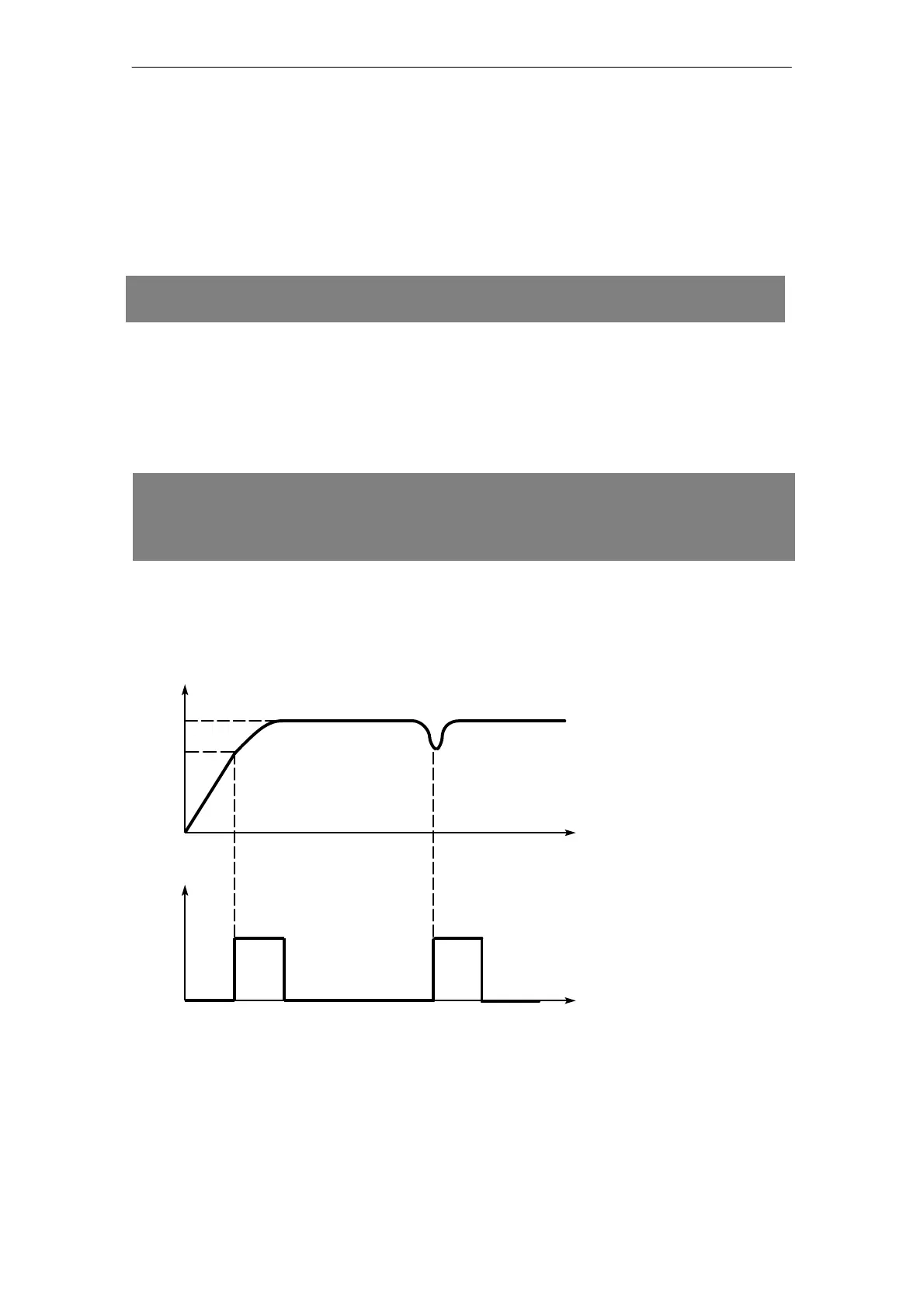
Voltage monitoring (reset)
A monitoring circuit monitors the module for voltage failures and dips in the 5 V supply. It
generates a defined reset pulse of < 10 ms for the microprocessor and the output registers
of the digital outputs when the power supply returns. Following this, the module must be
re-supplied with data and parameters.
"
,"*+"(% .(%,!
,
.
+, +,)*,#(' )*,#('
,
#! Reset pulse diagram