Technical Description
IP244
C79000–B8576–C859–02
2–6
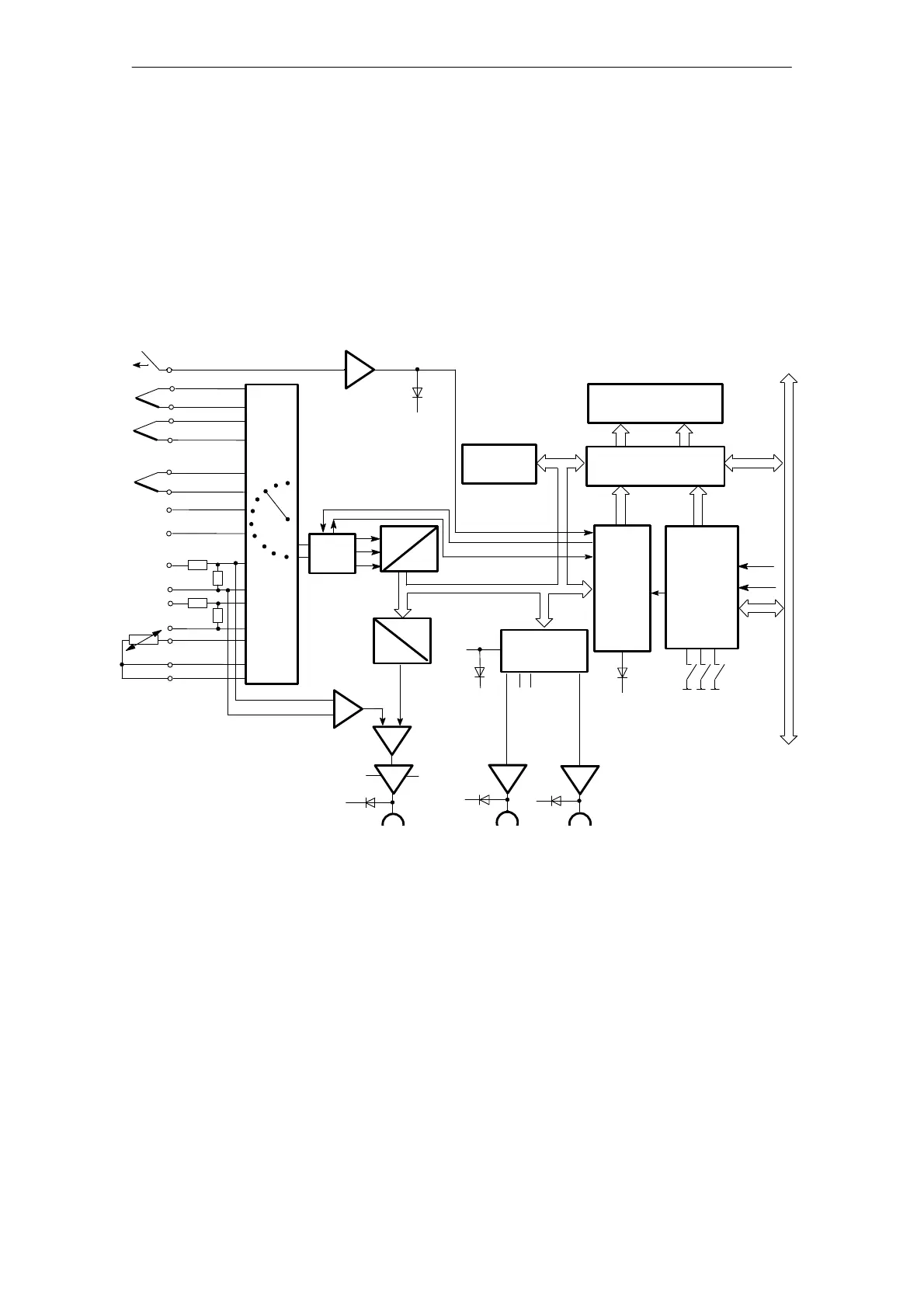
The various functions of the controller module are processed by the microprocessor:
– measured value acquisition via multiplexer and ADC
– measured value processing according to the control algorithm, (system error formation,
manipulated variable calculation, self-optimization)
– monitoring limit values of measured values and generation of interrupts
– output of manipulated variables via registers and output drivers
– calculation of the temperature compensation value according to the reference junction
temperature (Pt 100)
– comparison of an analog input value with a digital value (limit value monitoring disabled)
– controlling the interface to the S5 system bus
LED
red (U)
Comparator
M1
M13-
L -
LED (K)
DAU
L+
DQ 18
(K)
Differential
amplifier
5Ćbit
subĆaddresses
0
Channel no.
LED
(E)
15
1
7
Pt 100
Digital inputControl ON/OFF
L +
LED 1
R/W
13
BASP
Module address
8
14
LED
(R)
Analog signal
distribution
Wire break
detecton
internal data bus
Output
drivers
Semiconductor
multiplexer
Address
8/12Ćbit
address
+PESP
A
D
Register
17 Bit
P
Interface
logic
Collision
control
LED 17
DA 1DA17
EPROM
RAM
8Ćbit
data
Data/address
selection
S5 bus
D
A
Fig. 1.3/1 Block diagram of the temperature controller 244-3AA22
The module can be operated as a switching two or three step controller with percentage output
according to the control algorithm stored in the EPROM.
The controller action (P, PI, PD, PID) is selected by inputting the appropriate parameters. Data
(setpoints and parameters) is exchanged between the CPU and the temperature control module
by means of 64 messages each with a length of 32 bytes.