Data Exchange with the Central Controller
IP244
C79000–B8576–C860–02
4–28
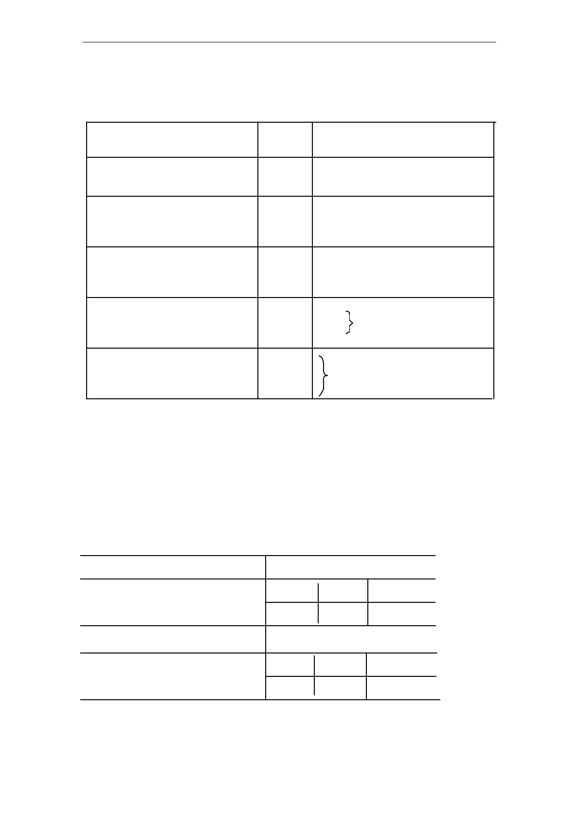
Byte 9 Control byte 2
Logical
state
1
0
Value of control bits 2
n
Required function
1
0
Setpoint ramping *
(not possible with selfĆtuning or
cascaded control)
Zone control
Manual operation (command "HB" in FB 162)
Automatic operation (command "AB" in FB 162)
Linearization of characteristic curve
and line break monitoring
0
1
Heating switch effective with this
controller
Heating switch not effective
1/0
1/0
1/0
1/0
Free
2
0
2
1
2
2
2
3
2
4
2
5
2
6
2
7
1
0
No
Yes
* (only possible with 2-step controllers with a heating function)
Bit 2
0
When switching over to manual operation the manual manipulated variable which
is entered in byte 10 is output.
Bit 2
3
If linear sensors (e.g. pyrosensors) are to be connected to the module, the
linearization of the characteristic curve stored in the firmware must be disabled.
Values must be entered in messages 30 to 42, bytes 0 and 1 for actual value
normalization.
If linearization is switched off, line break monitoring is also disabled.
Example 1
Required function
3Ćstep controller with
substitute thermocouple/Pt 100
Channel 7
Manual operation and zone control
Heating switch effective with the
controller
Control byte 1
0|1|1|1 1|0|0|1
0 1
7 9
hexadecimal
binary
hexadecimal
Control byte 2
0|0|0|0 0|0|0|1
binary
Required FunctionRequired function
The dual or hexadecimal representation of control bytes 1 and 2 according to the structure table
for examples 2 and 3 is as in example 1.