EasyManuals Logo
Home>Siemens>Control Unit>SIMOCODE pro C

Siemens SIMOCODE pro C User Manual

Siemens SIMOCODE pro C
408 pages
To Next Page IconTo Next Page
To Previous Page IconTo Previous Page
Page #218 background imageLoading...
Page #218 background image
Mounting, wiring, connecting, system interfaces, configuration guidelines
12.2 Wiring, connecting
SIMOCODE pro
218 System Manual, 05/2019, A5E40507475002A/RS-AD/004
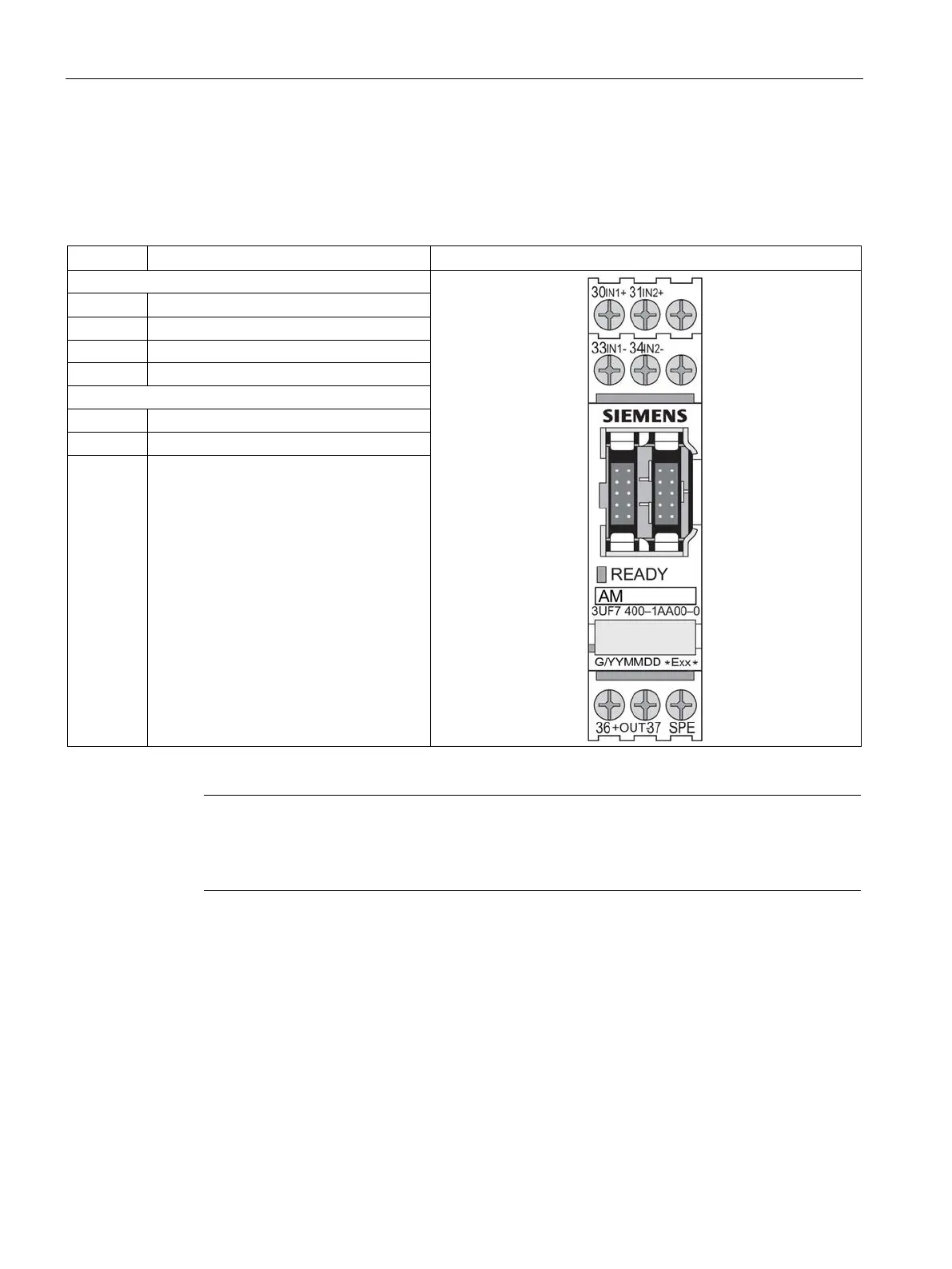
Terminal assignment of the analog module
The following table shows the assignment of the removable terminals:
Table 12- 16 Pin assignment of the removable terminals of the analog module
Terminal
Assignment
Upper terminals
30 Analog input IN1+
31
Analog input IN2+
33
Analog input IN1+
34
Analog input IN2+
Lower terminals
36
Analog output OUT+
37
Analog output OUT+
SPE
1)
System shielding
1)
Note
Conne
ct SIMOCODE pro via terminal SPE with the maximum possible cross-section and
with as short a cable as possible to the functional ground of the control cabinet,
e.g. to the grounded mounting plate of the control cabinet.

Table of Contents

Questions and Answers:

Question and Answer IconNeed help?

Do you have a question about the Siemens SIMOCODE pro C and is the answer not in the manual?

Siemens SIMOCODE pro C Specifications

General IconGeneral
BrandSiemens
ModelSIMOCODE pro C
CategoryControl Unit
LanguageEnglish

Related product manuals