Description of system components
8.8 Digital module (DM)
SIMOCODE pro
System Manual, 05/2019, A5E40507475002A/RS-AD/004
147
8.8 Digital module (DM)
Digital modules offer the option of further increasing the types and number of binary inputs
and relay outputs available at the SIMOCODE pro basic unit.
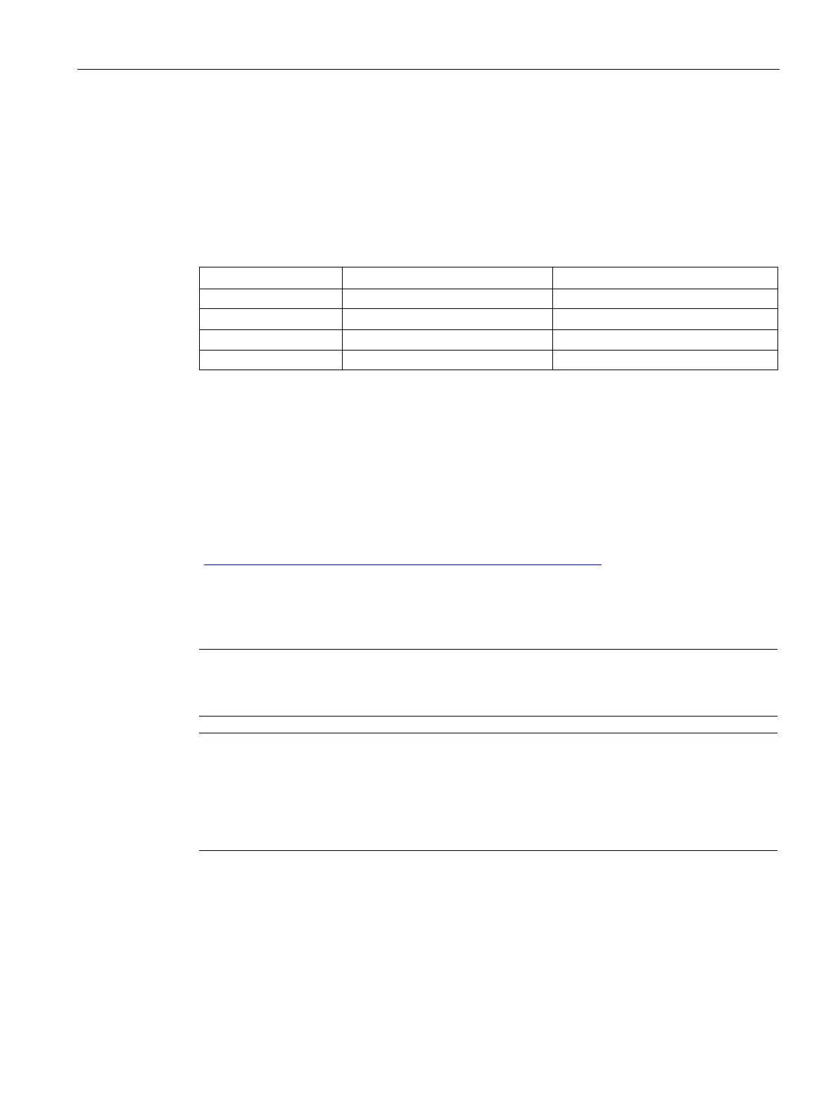
The following digital modules are available:
Table 8- 4 Versions of digital modules
2 monostable relay outputs
4 inputs External 110 V to 240 V AC/DC 2 monostable relay outputs
External 110 V to 240 V AC/DC
Up to 2 digital modules can be connected to one SIMOCODE pro basic unit. 4 additional
binary inputs and 2 additional binary outputs are thus provided by each module. All types
can be combined with each other. SIMOCODE pro can therefore be expanded to provide a
maximum of 12 binary inputs and 7 relay outputs.
With the monostable version, the relay outputs open after disconnection/failure/interruption
of the supply voltage. With the bistable version, the switching state of the relay outputs is
maintained even after disconnection/failure/interruption of the supply voltage.
You can set a debouncing time for the digital module inputs if required
(see Chapter "Digital module inputs" in the manual Parameterizing SIMOCODE pro
(https://support.industry.siemens.com/cs/ww/en/view/109743958
)).
Power supply to the inputs: See Chapter Wiring basic units, expansion modules and the
decoupling module (Page 195).
Note
To implement some motor control functions, a further digital module is required in addition to
th
e relay outputs on the basic unit.
digital modules are being used, the digital module connected the closest to the basic unit
via the system interface will be identified as digital module
1. The digital module connected
e identified as digital module 2. If one digital module is connected to the
front and another to the lower system interface of the basic unit, the digital module on the
front system interface of the basic unit will always be identified as digital module
1.