Commissioning, service, troubleshooting
13.2 Commissioning
SIMOCODE pro
274 System Manual, 05/2019, A5E40507475002A/RS-AD/004
13.2.4.4 Diagnostics via LED display on the basic unit and on the operator panel with
EtherNet/IP
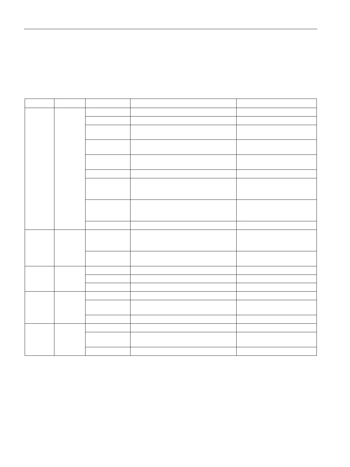
The basic unit and the operating panel have LEDs for displaying specific device states:
Table 13- 14 Diagnostics via LED display
Corrective measures for faults
Device Device
status
Green flickering Internal fault Send back the basic unit!
Yellow Memory module recognized, TEST/RESET
buttons control the memory module
_
Yellow flashing Memory module read in; factory settings
configured (duration: 3 s)
_
Yellow flickering Memory module programmed
_
Device defective (also GEN. FAULT on)
Red – flashing Memory module or expansion modules
defective (also GEN. FAULT on - flashing)
Reprogram/replace the memory
module, replace the expansion
Off Supply voltage too low Check whether the supply
voltage is connected/switched
PE energy saving mode active
Bus Bus status Off No communication with a controller active Connect the bus or check
Ethernet parameters (IP
Green flashing Communication with a controller active
(e.g. Rockwell Automation controller)
_
GEN.
FAULT
Fault
status
Fault pending; reset has been saved
Rectify fault, e.g., overload
Fault pending; reset has not been saved
PORT1
(only on
basic unit)
Bus status
Ethernet connection available
Off No Ethernet connection available Check the Ethernet connection
Station flash test for device location active
PORT2
(only on
basic unit)
Bus status
Ethernet connection available
Off No Ethernet connection available Check the Ethernet connection
Station flash test for device location active