– Screw the jack screws into the forcing plate. Ensure that the jack screws protrude evenly
from the forcing plate. There must be a minimum distance of 50mm between the non-
magnetic counter-bearing blocks and the forcing plate.
– Place a spacer foil between the primary section and the secondary section track.
– Screw back the jack screws in steps to lower the primary section onto the secondary
section track, in parallel and centered with it.
– Then completely remove the forcing assembly from the primary section.
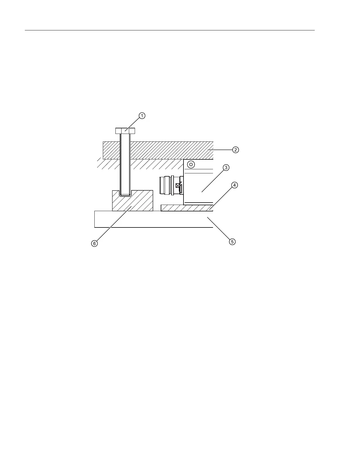
① Jack screw
② Forcing plate
③ Primary section
④ Spacer foil
⑤ Secondary section
⑥ End support block (aluminum/brass)
Figure5-5 Remove the forcing o xture from the primary section (similar diagram)
3. Installing the primary section on the slide.
– Secure the slide on the guides.
– Push the slide over the primary section. When doing this, the mounting holes of the
primary section and slide must be fully aligned.
– The mounting screws are initially screwed through the slide into the primary section and
tightened by hand. By uniform and alternating tightening of the mounting screws, the
primary section is lifted from the secondary section track.
Installation
5.3Procedure when installing the motor
Naturally-Cooled 1FN3 Linear Motors
68 Operating Instructions, 06/2023, A5E52220465B AB