Installation
4-59
E Siemens AG, 2003 All rights reserved
SIMOTION C230-2, 04.2003 Edition
4.1.2 Clearances
Rules
If you comply with the minimum clearances, you will:
S Ensure heat is dissipated from the modules
S Provide space to fit and remove modules
S Provide space to lay wiring
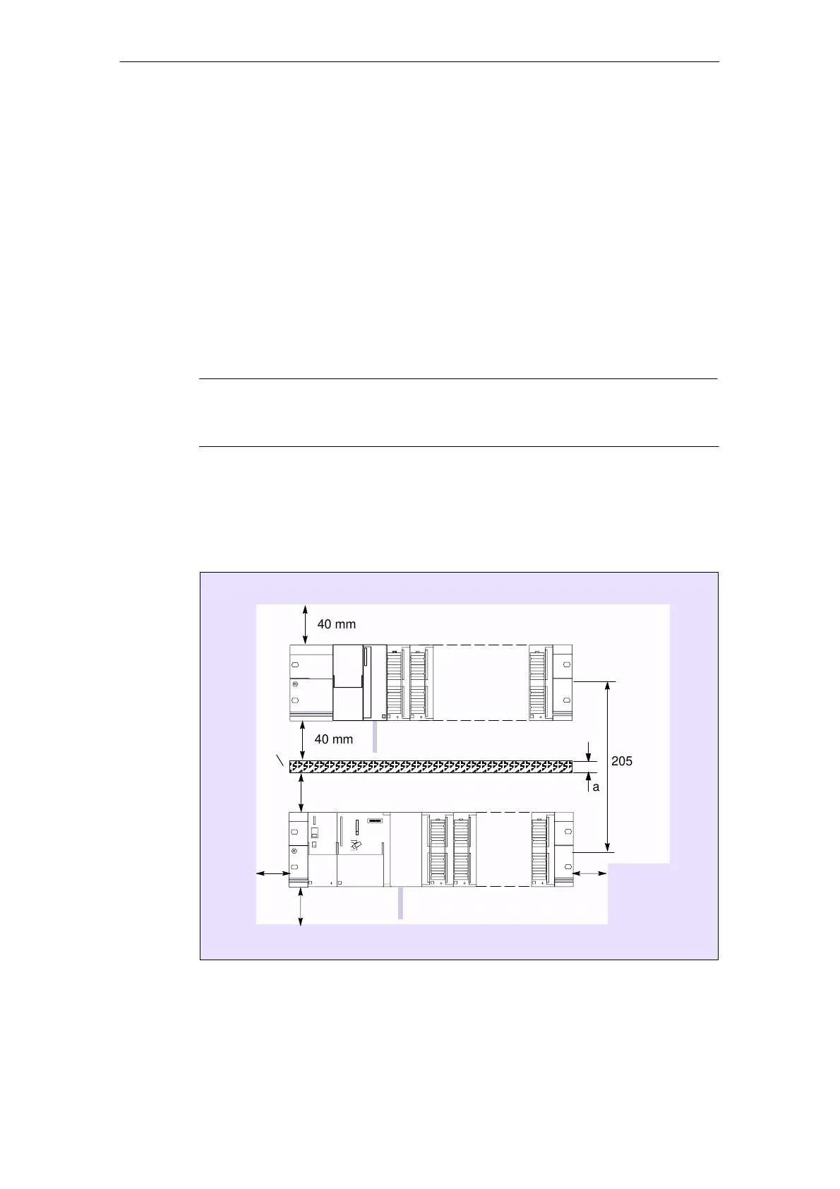
S Increase the mounting height of the rack to 205 mm
To guarantee the functionality, clearances of 40 mm must be maintained.
Note
If you use a shield connecting element (see Section 6.3), the dimensions stated
are measured from the lower edge of the shield connecting element.
Clearances
Fig. 4-2 shows the clearances between the individual racks and the clearance to
adjacent equipment, cable ducts, cabinet walls, etc.
40 mm
40 mm
20
mm
20
mm
40 mm
40 mm
a
205 mm
+ a
E.g. cable duct
Fig. 4-2 Clearances
 Loading...


