Device Data
3-22
E Siemens AG, 2003 All rights reserved
SIMOTION C230-2, 04.2003 Edition
Display of LEDs
The following LEDs are on the front panel of the C230-2. The LEDs and their func-
tion are described in Table 3-2.
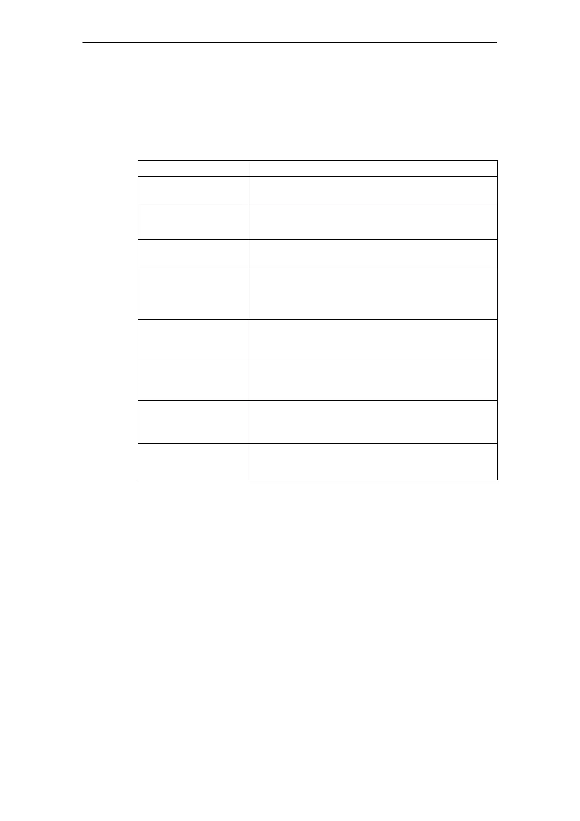
Table 3-2 Status and fault displays
LED
Function
SF (red) This LED indicates a fault on the C230-2.
(See Section 3.3)
5 VDC (green) This LED indicates that the power supply for the electronics is
ready.
(See Section 3.3)
RUN (green) -
C230-2 in RUN
This LED indicates that the user program is running.
(See Section 3.3)
STOPU (yellow) –
C230-2 in STOP User
Program
This LED indicates that the technology packages (e.g.
synchronous operation, cam) are active. The user program is
not active.
(See Section 3.3)
STOP (yellow) –
C230-2 in STOP
This LED indicates that no user program is running. The
technology packages are not active.
(See Section 3.3)
BUS1F (red) –
group fault
This LED indicates a fault on the C230-2’s PROFIBUS DP1
interface (X8).
(See Section 3.3)
BUS2F (red) –
group fault
This LED indicates a fault on the C230-2’s PROFIBUS DP2
/MPI interface (X9).
(See Section 3.3)
Q0...Q7, I0...I11,
B1...B4, M1, M2 (green) –
digital inputs/outputs
These LEDs show the status of the digital inputs/outputs.
(See Subsection 3.1.8)
Control elements
Mode selector
Certain operating modes can be selected using the mode selector (see Subsec-
tion 3.1.1).
 Loading...


