Wiring
6-96
E Siemens AG, 2003 All rights reserved
SIMOTION C230-2, 04.2003 Edition
6.2.4 Wiring the front connector
Wiring the front connector
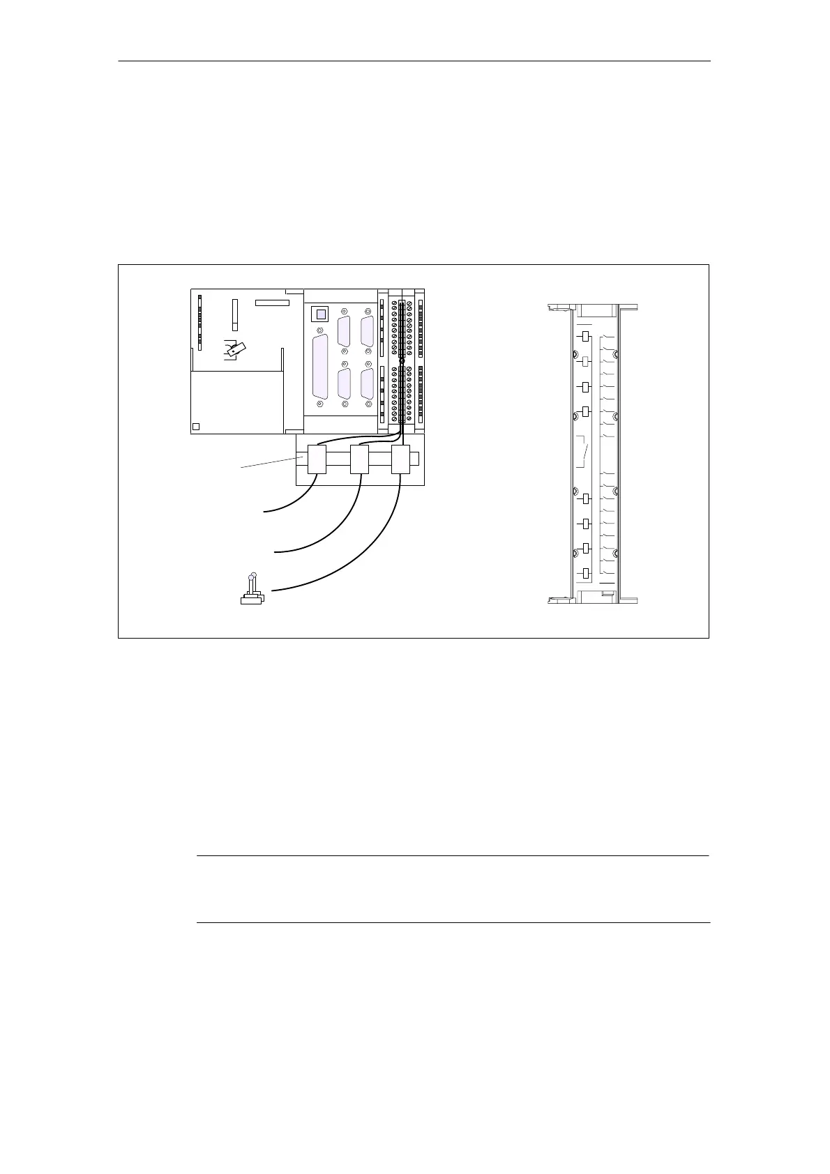
Fig. 6-10 shows how the cables are routed to the front connector and how to sup-
press line interference through the use of the shield connecting element.
C230-2
2 x measuring inputs
READY contact
Shield connecting element
Labeling of inside cover
Digital inputs/outputs
X2
X3 X4
X6X5
X1
SIEMENS
10
8
6
4
2
1
11
13
15
37
38
39
28
27
26
25
24
23
22
30
31
32
33
34
35
36
17
19
20 40
M
L+
29
M
C230-2
X7
Fig. 6-10 Wiring the front connector
Connecting cables
Flexible cable, cross section 0.25 to 1.5 mm
2.
Connector sleeves are not required.
You can use connector sleeves without an insulating collar in accordance with
DIN 46228, Form A long version.
You can connect two lines, each 0.25 to 0.75 mm
2
, in one connector sleeve.
Note
In order to obtain optimum interference suppression, a shielded cable is required
to connect measuring inputs or BEROs.
 Loading...


