Supplementary system components
6.4 CX32-2 controller extension
SIMOTION D4x5-2
Manual, 11/2010
97
Connection and circuit diagram
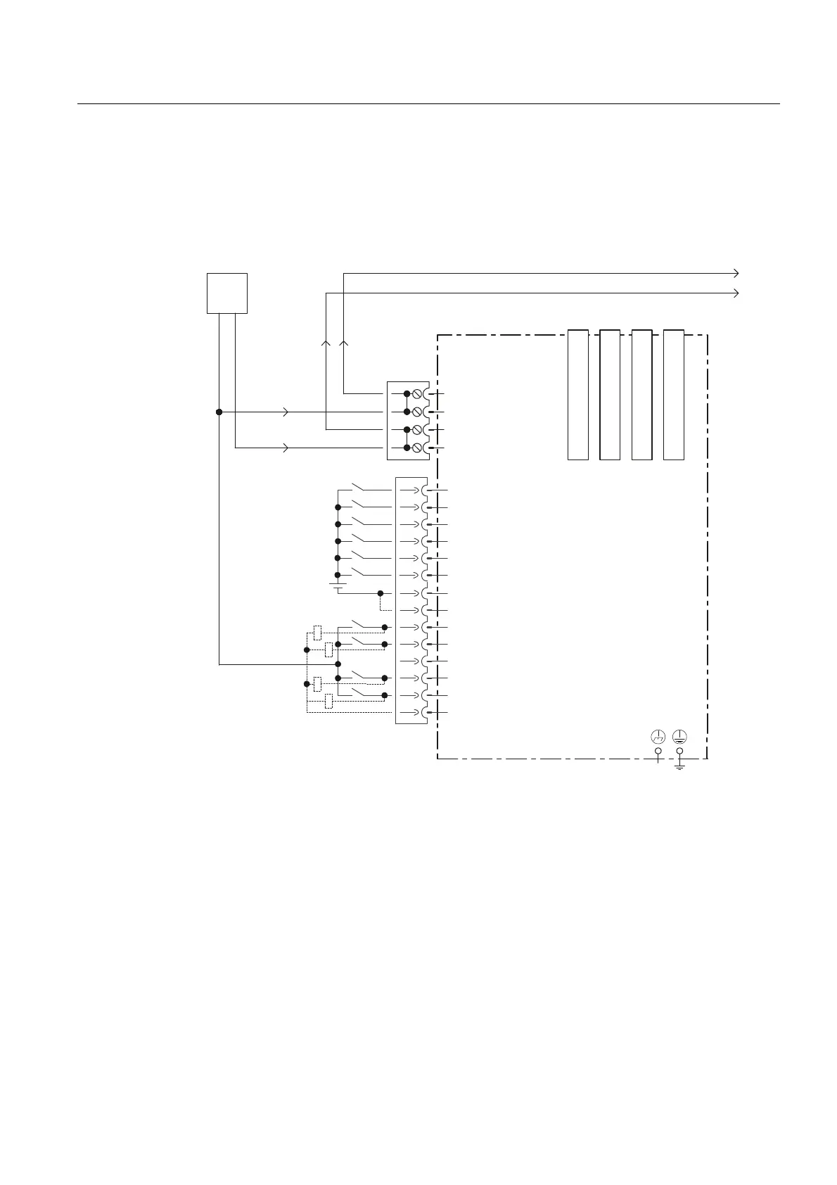
The following figure shows the schematic diagram and the connection of the digital
inputs/outputs on the CX32-2 and the associated external power supply.
-XPSHURSHQHOHFWULFDO
LVRODWLRQIRUGLJLWDOLQSXWV',
&DQEHLQGLYLGXDOO\
SDUDPHWHUL]HGDVLQSXWRXWSXW
([W
&;FRQWUROOHUH[WHQVLRQ
0
0
','2
','2
','2
0
0
',
',
',
',
','2
;
',
',
; ; ; ;
;
0
0
0
0
9
0
0
9
'5,9(&/L4%XFKVH
'5,9(&/L4%XFKVH
'5,9(&/L4%XFKVH
'5,9(&/L4%XFKVH
Figure 6-8 Digital inputs/outputs connection diagram

 Loading...


