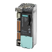
Supplementary system components
6.4 CX32-2 controller extension
SIMOTION D4x5-2
98 Manual, 11/2010
Interface assignment of X122
Table 6- 15 Digital inputs/outputs X122
Pin Designation
1)
Signal type
2)
Notes
1 DI 0 I Digital input 0
2 DI 1 I Digital input 1
3 DI 2 I Digital input 2
4 DI 3 I Digital input 3
5 DI 16 I Digital input 16
6 DI 17 I Digital input 17
7 M1 GND Ground for DI 0 – DI 3, DI 16, DI 17 (electrically isolated
relative to M)
8 M GND Ground
9 DI/DO 8 B Digital input/output 8 (can also be used as input for measuring
input or as input for the external zero mark)
10 DI/DO 9 B Digital input/output 9 (can also be used as input for measuring
input or as input for the external zero mark)
11 M GND Ground
12 DI/DO10 B Digital input/output 10 (can also be used as input for
measuring input or as input for the external zero mark)
13 DI/DO 11 B Digital input/output 11 (can also be used as input for
measuring input or as input for the external zero mark)
14 M GND Ground
1)
DI: Digital input; DI/DO: Bidirectional digital input/output; M: Electronics ground;
M1: Ground reference
2)
B = Bidirectional; I = Input; GND = Reference potential (ground)
Note
An open input is interpreted as "Low".
Terminal M1 must be connected for the digital inputs to function. The following alternatives
are available:
Connect the incorporated ground reference of the digital input to M1.
Create the bridge between terminal M and terminal M1.
This removes the electrical isolation for these digital inputs.

 Loading...


