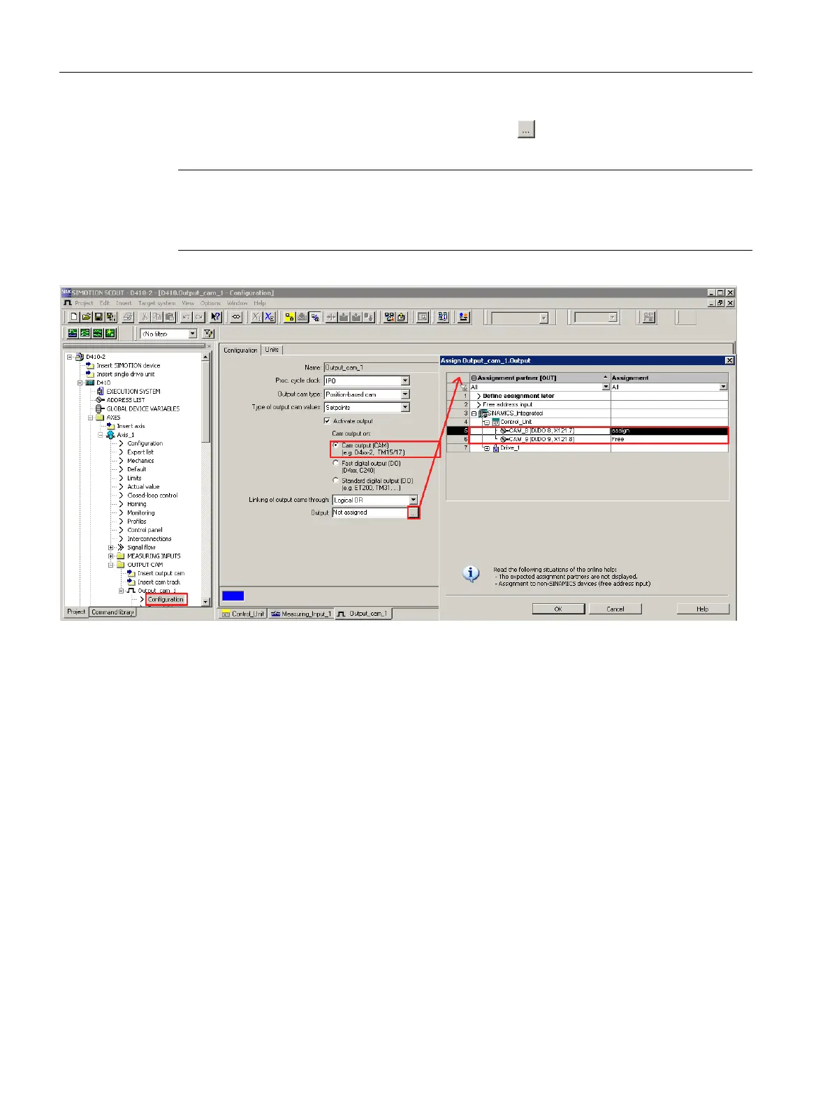
Then assign a hardware output. For this purpose, click ("assign") to open the Assignment
dialog box and select a free (i.e. not yet used) I/O.
Note
Only those I/Os that have the appropriate functionality (DO_xx [channel name, terminal
number]) are displayed. If no suitable I/Os are displayed, you must first configure the I/Os (I/
O must be configured as "output cam (CAM)")
Figure 7-34 Configuration of a cam for SIMOTION D410-2
A maximum of 2 edges can be output per processing cycle clock of TO outputCam or TO
camTrack.
Additional references
Detailed information on configuring the output cam and cam track technology objects can be
found in the
SIMOTION Output Cams and Measuring Inputs
Function Manual.
Commissioning (software)
7.11 Configuring technology objects and I/O variables
SIMOTION D410-2
214 Commissioning and Hardware Installation Manual, 01/2015
 Loading...


