We recommend that you set method 2.
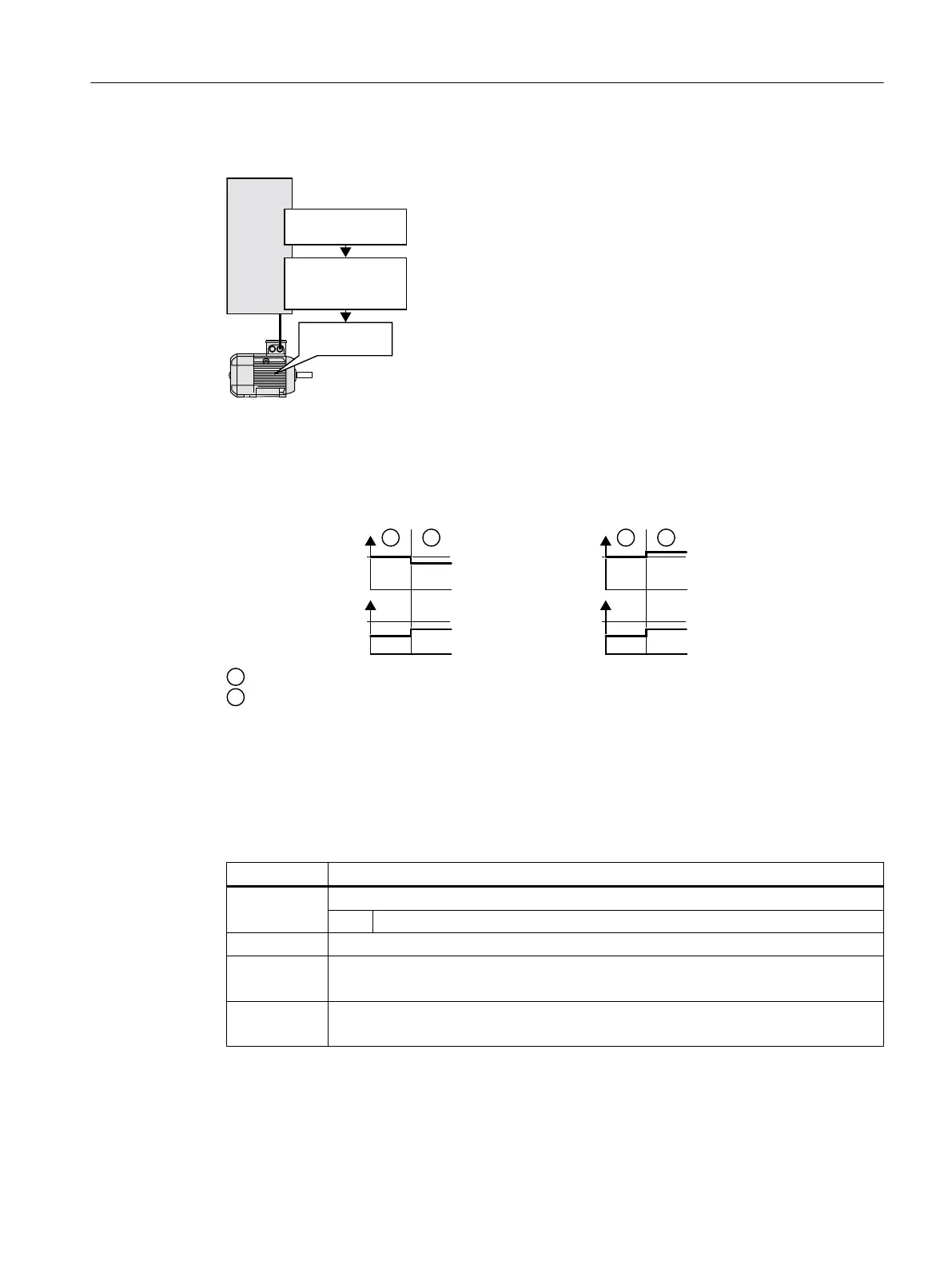
,QYHUWHU
7KHUPDOPRWRU
PRGHO
(IILFLHQF\
GHSHQGHQWRQWKH
IOX[
2SWLPXPIOX[
Figure 6-58 Determining the optimum flux from the motor thermal model
Based on its thermal motor model, the inverter continually determines - for the actual operating
point of the motor - the interdependency between efficiency and flux. The inverter then sets
the flux to achieve the optimum efficiency.
)OX[
(IILFLHQF\
)OX[
(IILFLHQF\
(IILFLHQF\RSWLPL]DWLRQLVQRWDFWLYH
(IILFLHQF\RSWLPL]DWLRQLVDFWLYH
Figure 6-59 Qualitative result of efficiency optimization, method 2
Depending on the motor operating point, the inverter either decreases or increases the flux in
partial load operation of the motor.
The inverter calculates the parameters for the thermal motor model based on the motor data
that has been set – and the motor data identification.
Parameter Description
p1401 Flux control configuration
.14 1 signal: Efficiency optimization 2 active
p1570 Flux setpoint (factory setting: 100%)
p3315 Efficiency optimization 2 minimum flux limit value (factory setting: 50%)
Minimum limit value for the calculated optimal flux
p3316 Efficiency optimization 2 maximum flux limit value (factory setting: 110%)
Maximum limit value for the calculated optimal flux
Advanced commissioning
6.35 Efficiency optimization
Converter with the CU230P-2 Control Units
Operating Instructions, 09/2017, FW V4.7 SP9, A5E34257946B AE 349

 Loading...


