Additional system components
7.3 Sensor Module Cabinet-Mounted SMC30
SINAMICS DCM DC Converter
Operating Instructions, 12/2018, A5E34763375A
211
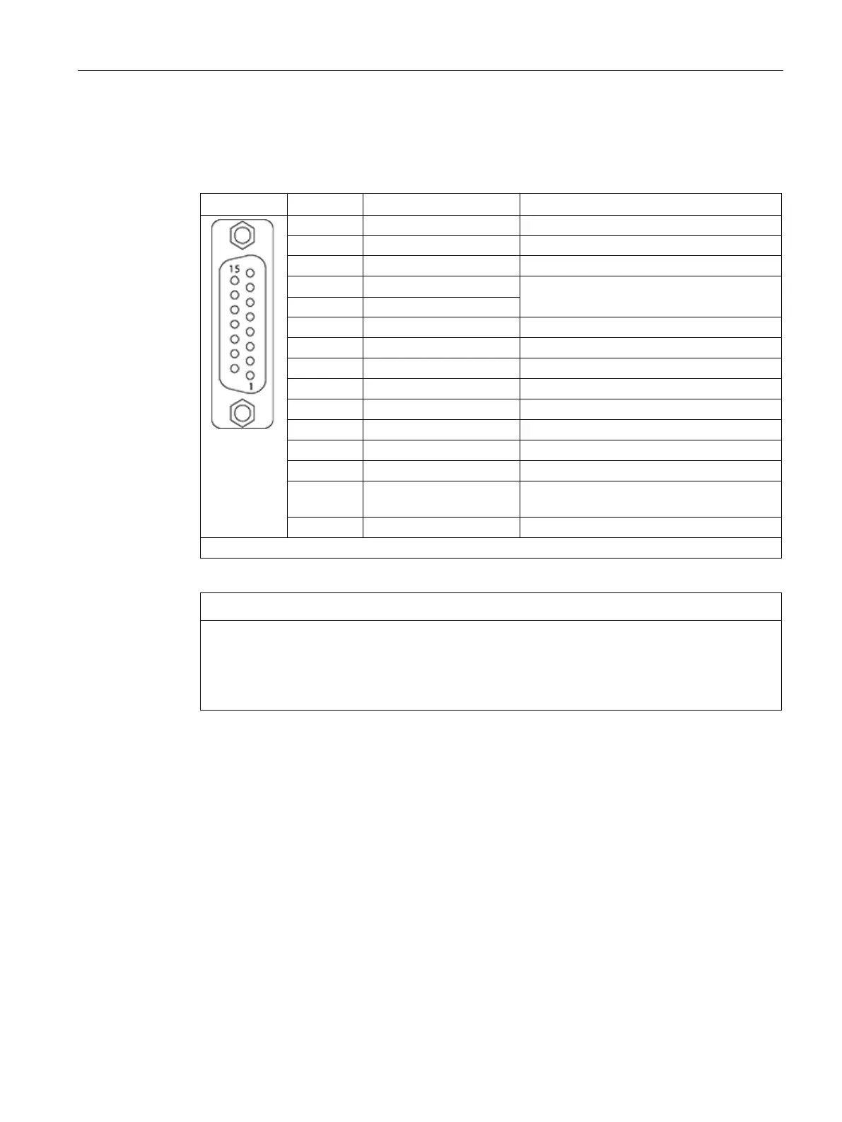
X520 encoder system interface
Table 7- 15 X520 encoder system interface
4 P encoder 5 V/24 V Encoder supply
Sense input, encoder supply
Inverse reference signal R
Inverse incremental signal B
14 A*/data* Inverted incremental signal A/inverted SSI
Incremental signal A/SSI data
Connector type: SUB-D female, 15-pin
Destruction of the encoder due to an incorrect supply voltage
The encoder supply voltage can be assigned as 5 V or 24 V. The encoder may be
destroyed if you enter the wrong parameters.
• Select the appropriate motor supply voltage.

 Loading...


