EasyManuals Logo

Siemens SINAMICS Series User Manual

Siemens SINAMICS Series
758 pages
To Next Page IconTo Next Page
To Previous Page IconTo Previous Page
Page #653 background imageLoading...
Page #653 background image
Descriptions of functions
10.34 Diagnostics
SINAMICS DCM DC Converter
Operating Instructions, 12/2018, A5E34763375A
651
10.34.6.2
Buffer for faults and alarms
Note
A fault buffer and alarm buffer are provided for each drive.
The drive and device-specific
messages are entered in these buffers.
The contents of the fault buffer are saved to the non
-volatile memory when the Control Unit
is powered down, i.e.
the fault buffer history is still available when the unit is powered up
a
gain.
Note
The entry in the fault/alarm buffer is made after a delay. For this reason, the fault/alarm
buffer should not be read until a change in the buffer is also recognized (r0944, r2121) after
"
Fault active"/"Alarm active" is output.
Fault buffer
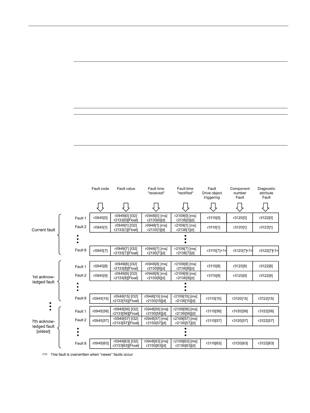
Faults which occur are entered in the fault buffer as follows:
Figure 10-99 Structure of the fault buffer

Table of Contents

Other manuals for Siemens SINAMICS Series

Questions and Answers:

Question and Answer IconNeed help?

Do you have a question about the Siemens SINAMICS Series and is the answer not in the manual?

Siemens SINAMICS Series Specifications

General IconGeneral
Product LineSINAMICS
Cooling MethodAir-cooled, Liquid-cooled
Voltage Range200 V to 690 V
Power Range0.12kW - 250kW
Communication InterfacesPROFINET, PROFIBUS, Ethernet
Control ModesVector control, V/f control
Protection ClassIP20
TypeVariable Frequency Drives (VFD)

Related product manuals