Additional system components
7.3 Sensor Module Cabinet-Mounted SMC30
SINAMICS DCM DC Converter
214 Operating Instructions, 12/2018, A5E34763375A
Connection examples
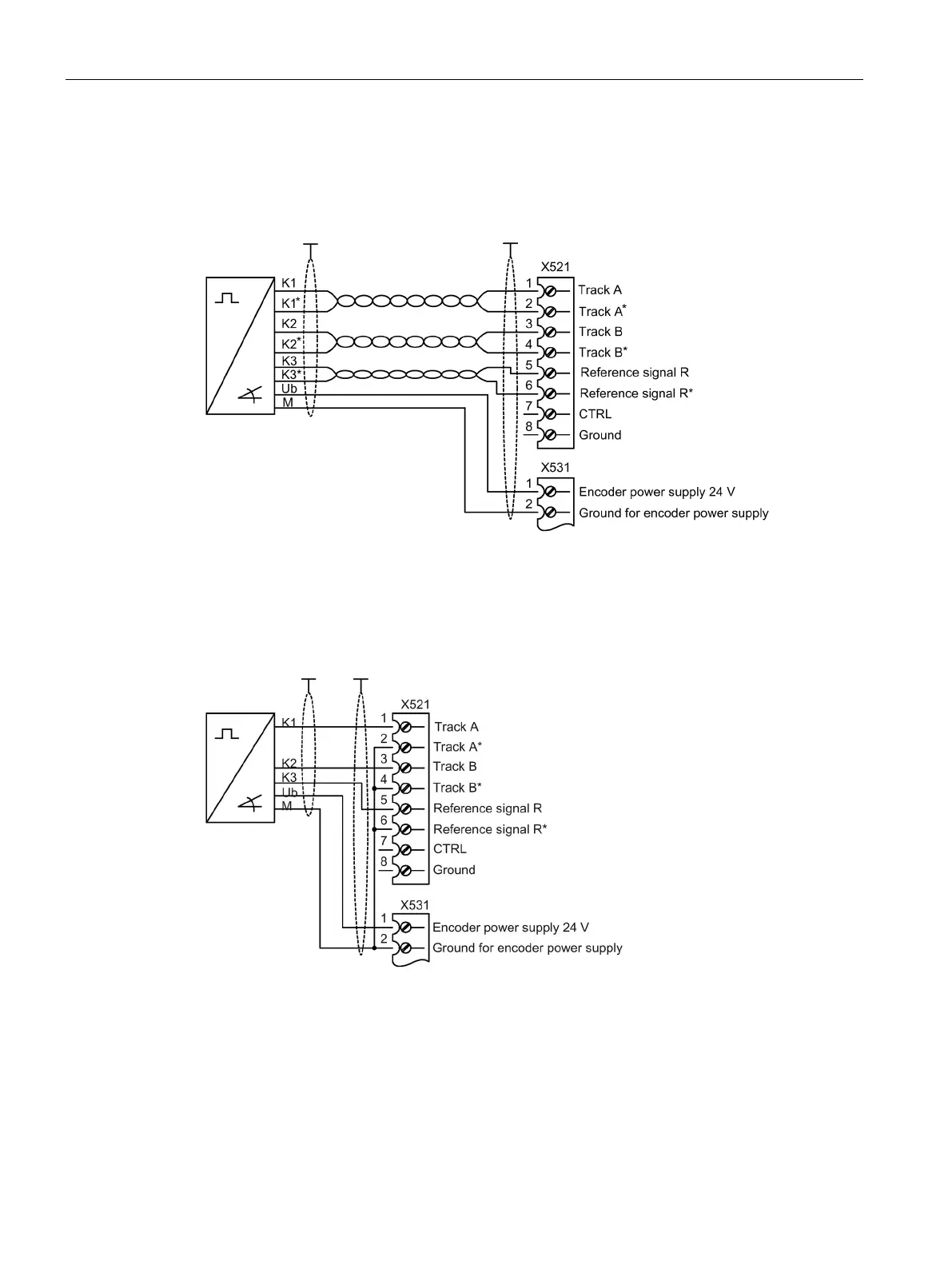
Connection example 1: HTL encoder, bipolar, with reference signal
Figure 7-8 Connection example 1: HTL encoder, bipolar, with reference signal
Signal cables must be twisted in pairs in order to improve resistance to induced interference.
Connection example 2: HTL encoder, unipolar, with reference signal
Figure 7-9 Connection example 2: HTL encoder, unipolar, with reference signal
1)
1)
Because the physical transmission properties are more robust, the bipolar connection
should always be used. The unipolar connection should only be used if the encoder type
does not output push-pull signals.

 Loading...


