Additional system components
7.3 Sensor Module Cabinet-Mounted SMC30
SINAMICS DCM DC Converter
Operating Instructions, 12/2018, A5E34763375A
221
"Zero pulse inactive time"
(before and after A=B=high)
t
Lo
640 (t
ALo-BHi
- t
Hi
)/2
3)
ns
"Zero pulse active time"
(while A=B=high and beyond)
4)
t
Hi
640 t
ALo-BHi
- 2*t
Lo
3)
ns
Other signal levels according to the RS422 standard
The absolute level of the individual signals varies between 0 V and V CC of the encoder system.
t
ALo-BHi
is not a specified value, but is the time between the falling edge of track A and the next but one rising edge of
track B.
Additional information on setting the "Zero pulse active time" can be found in the Function Manual: /FH1/ SINAMICS
S120, tolerant encoder monitoring for SMC30.
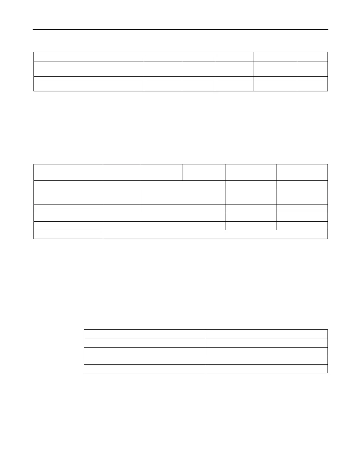
Table 7- 20 Connectable encoders
HTL unipolar 24 V
1)
No/yes Yes (however, a bipolar
connection is recommended)
1)
No No
Because the physical transmission properties are more robust, the bipolar connection should always be used. The
unipolar connection should only be used if the encoder type does not output push-pull signals.
A controller compares the encoder system supply voltage - sensed via the Remote Sense cables - with the reference
supply voltage of the encoder system, and adjusts the supply voltage for the encoder system at the output of the drive
module until the required supply voltage is obtained directly at the encoder system (only for 5 V encoder system power
Maximum encoder cable length
Table 7- 21 Maximum encoder cable length
Maximum encoder cable length in m
1)
2)
For TTL encoders at X520 → Remote Sense → 100 m
Because the physical transmission properties are more robust, the bipolar connection should
always be used. The unipolar connection should only be used if the encoder type does not output

 Loading...


