Additional system components
7.4 Terminal Module TM15
SINAMICS DCM DC Converter
236 Operating Instructions, 12/2018, A5E34763375A
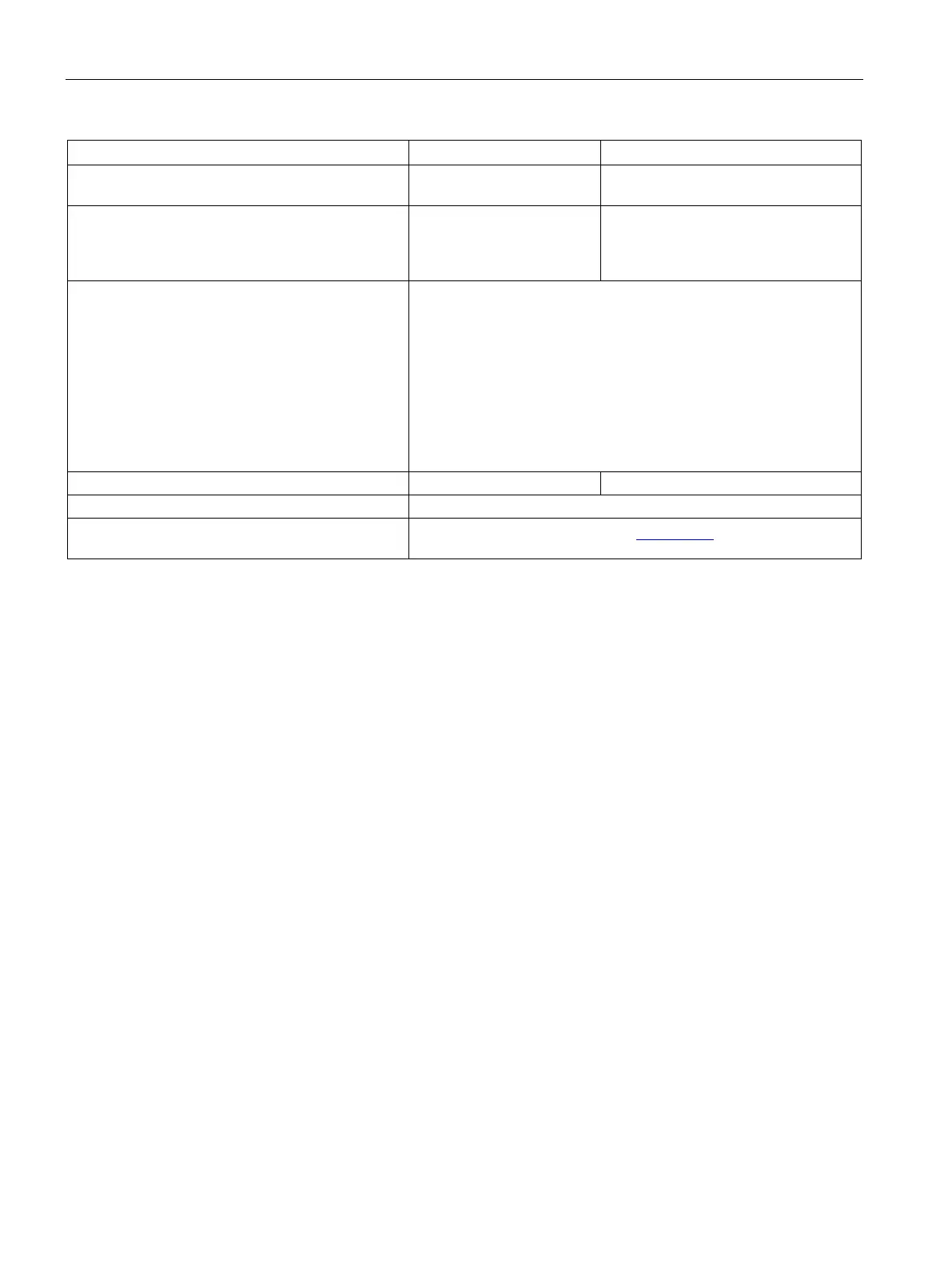
Voltage drop, output
(I/O power supply to the output)
V
DC
0.5
Max. total current of outputs (per group)
up to 60 °C
up to 50 °C
A
DC
A
DC
2
3
Response time The response time for the digital inputs/outputs (TM15 DI/DO)
consists of the following elements:
• Response time on the component itself
(approx. 1/2 DRIVE-CLiQ clock cycle).
• Transmission time via the DRIVE-CLiQ connection
(approx. 1 DRIVE-CLiQ clock cycle).
• Evaluation on the Control Unit (see function diagram)
For additional information:
SINAMICS DCM List Manual, Chapter "Function block diagrams"
Protective conductor connection
On enclosure with M4/1.8 Nm screw
Approvals UL and cULus, http://www.ul.com (www.ul.com)
File: E164110, Vol. 2, Sec. 9

 Loading...


